The carburettor is the mixture control
On an engine without electronic injection, the carburettor (or carb) turns inlet airflow into a metered fuel quantity. A performance change that increases airflow, camshaft overlap, exhaust scavenging or engine speed will usually make the original needles or jets wrong somewhere in the range. The symptom is a flat spot, a rich stumble, or a lean full-throttle run. The cure is a metering change for that carburettor and that engine, not a jet size copied from a different engine.
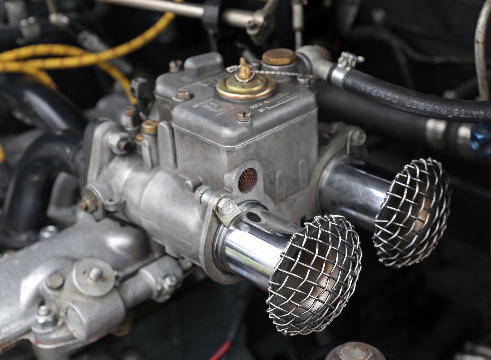

Two main families cover most automotive installations, alongside mechanical slide-throttle motorcycle carbs. A variable-choke carburettor, of which the SU is the usual example, changes the size of the air passage. A fixed-choke carburettor keeps the venturi size and uses more than one fuel circuit because the air speed through that venturi changes with throttle and engine speed. See carburettor types and layouts for the full family breakdown and fuel circuits and metering for cut-away diagrams of each circuit.
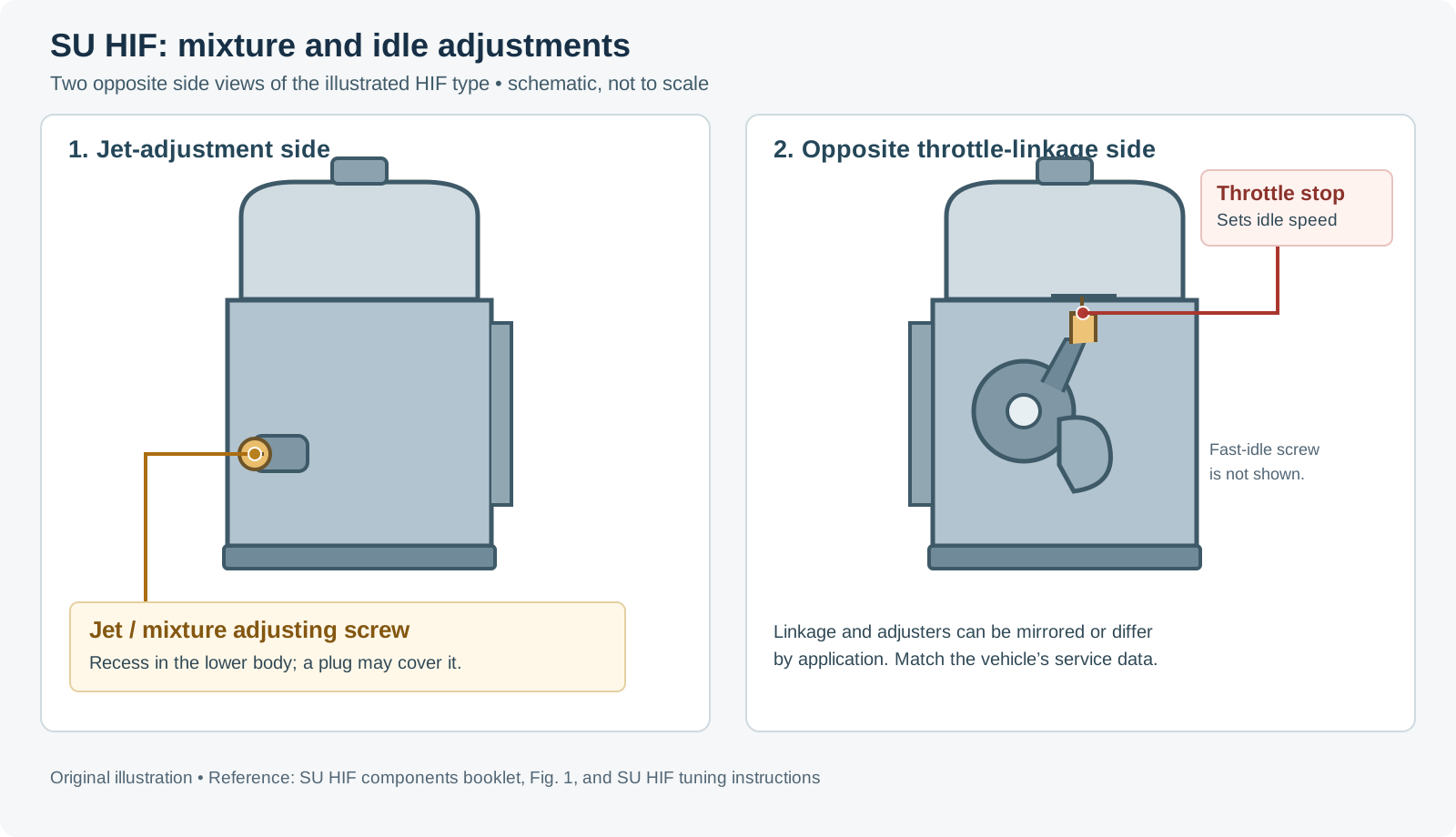
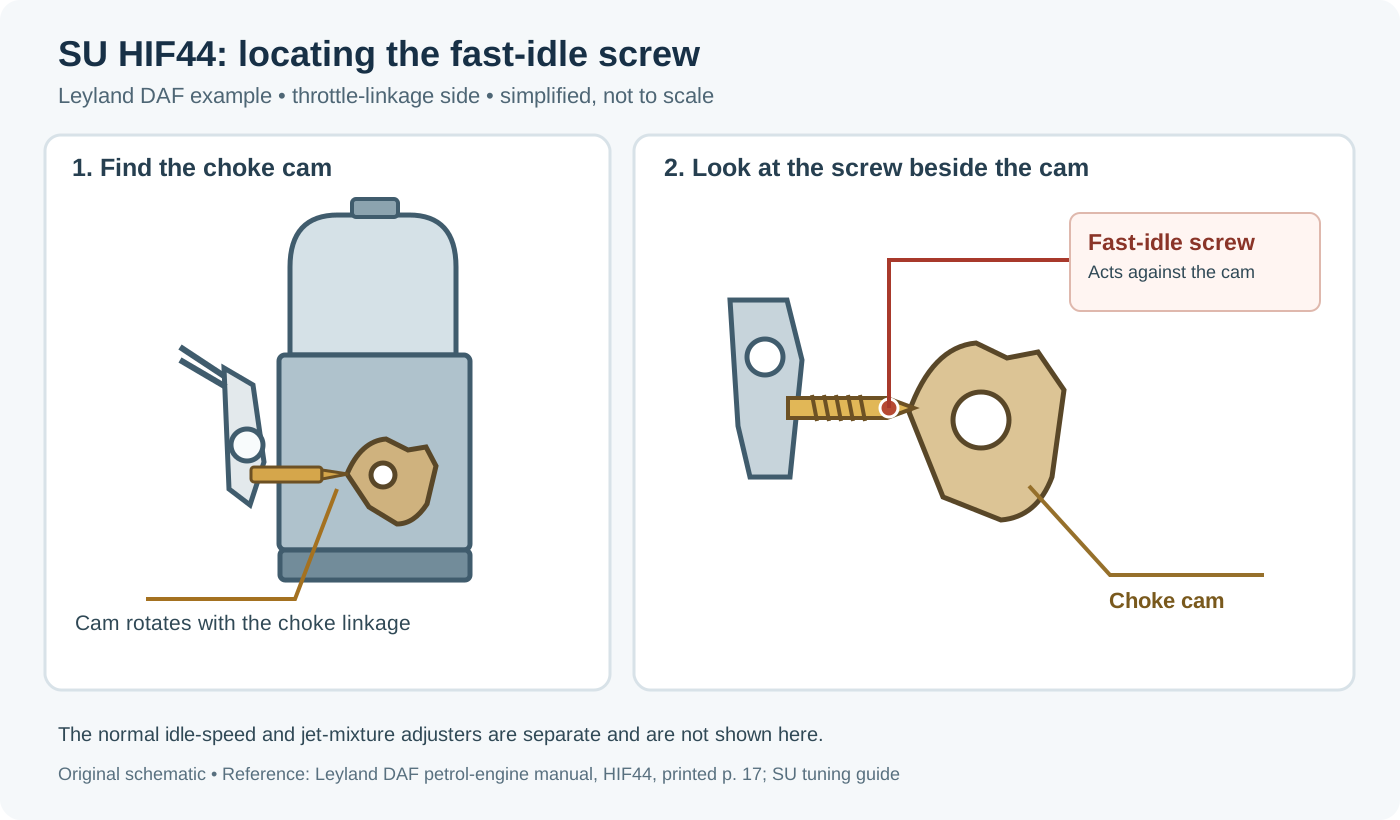
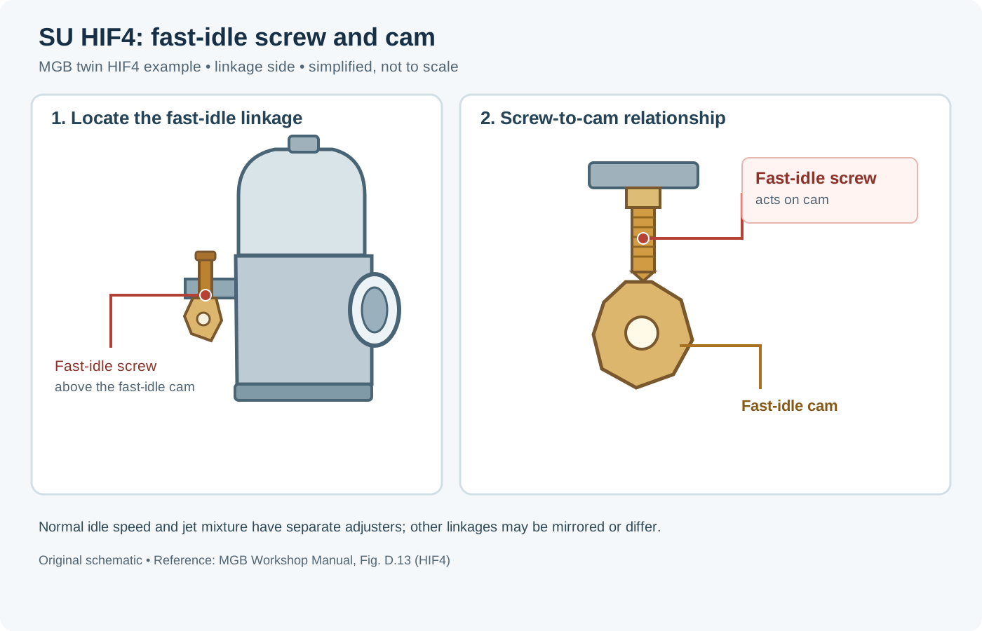
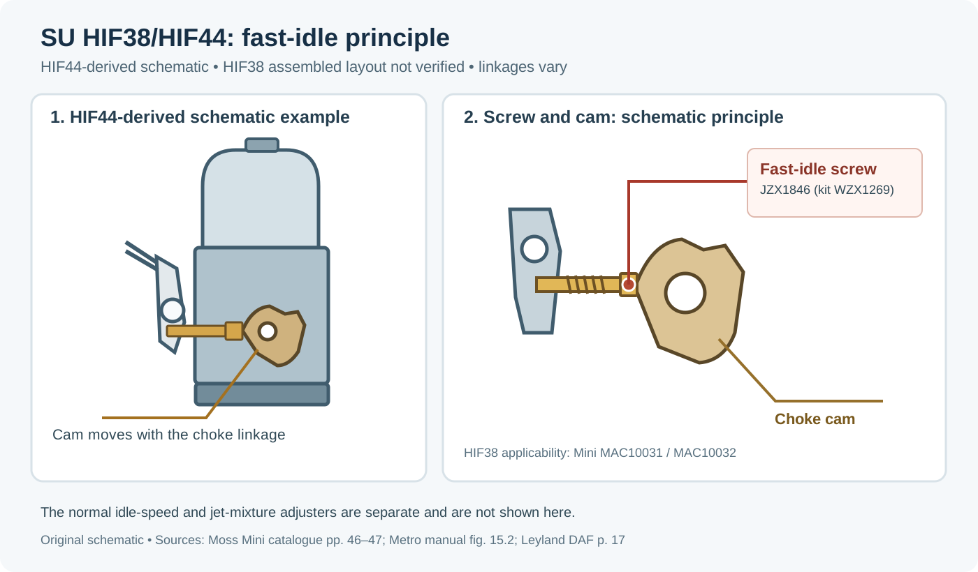
Example: identifying idle adjusters
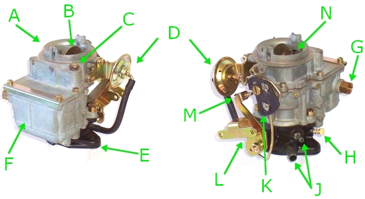

Before touching any jet: prerequisites
Setting the ignition and the mechanical baseline before judging mixture saves hours of chasing phantom carburettor faults. A weak or uneven cylinder looks like a carburettor fault.
- Compression, valve clearances and ignition: confirm even cylinder compression, correct tappet/valve clearances, sound HT leads and plugs, and verified base ignition timing plus mechanical and vacuum advance curves.
- Zero vacuum leaks: check inlet manifold gaskets, carburettor base gaskets, servo hoses and throttle shafts for unmetered air leaks.
- Fuel pressure and float height: verify regulated fuel pressure matches the carburettor's needle-valve design and set float level (dry height/drop or wet well depth) first. An incorrect float level alters the effective richness of every downstream circuit. Pressure ranges by family are given in carburettor fuel supply.
- Synchronise multiple carbs: on multi-carburettor engines the throttles and pistons have to move together. Balancing the airflow before chasing a needle or idle jet stops one cylinder correcting for another (synchronisation and fault diagnosis).
Choosing venturi (choke) size and CFM capacity
A common error when fitting aftermarket carbs is choosing too large a venturi or too high a CFM rating. Venturi depression depends on air velocity; oversized chokes reduce signal at low and mid engine speeds, hurting atomisation, off-idle progression and part-throttle torque.
- Individual-runner fixed-choke (Weber DCOE / IDF / Dell'Orto DHLA): the interchangeable main choke (venturi) is selected around cylinder capacity and peak-power RPM so velocity stays high enough for clean fuel draw while avoiding top-end choking.
- Four-barrel plenum carbs (Holley / Edelbrock / Quadrajet): required airflow scales roughly with displacement, maximum RPM and volumetric efficiency; heavy street vehicles with automatic transmissions generally respond better to crisp primary velocity and properly tuned vacuum secondaries than to an oversized mechanical-secondary carburettor (Holley 4160 manual). Holley's sizing formula is given on the Holley 4150 and 4160 page.
Systematic tuning order
Because carburettor circuits overlap from closed throttle to wide-open throttle, tune them from the ground up rather than changing main jets to cure a low-speed hesitation:
- Float level and fuel pressure (sets the baseline fuel head).
- Idle speed and idle mixture (throttle blade closed onto the idle stop so the progression/transfer slots are not uncovered; adjust mixture screws for highest, smoothest idle or target idle AFR/CO).
- Off-idle and cruise / progression (idle/progression jet on Weber/Dell'Orto, slow jet/air screw and slide cutaway on motorcycle slide carbs, primary cruise jet/metering rod on four-barrels).
- Mid-range transition (emulsion tube on Weber/Dell'Orto, needle taper and clip position on slide carbs, needle profile on SU/Stromberg).
- Wide-open throttle and high RPM (main jet for overall WOT mixture, air corrector jet to trim high-RPM enrichment or lean-off, power valve or step-up spring for load-based enrichment).
- Transient response (accelerator pump nozzle size and cam profile, secondary diaphragm spring on vacuum-secondary four-barrels, damper oil viscosity on SU/Stromberg).

Tuning by carburettor family
Variable choke: SU and Zenith-Stromberg
The 1958 SU workshop manual describes the carburettor as an automatically expanding choke. The piston rises and falls with manifold suction, which itself depends on how far the throttle is open and on load. As the piston rises it opens a larger air passage over the single jet, and the tapered needle fixed to the piston opens a larger fuel area at the same time to keep air speed over the jet roughly constant—so a separate idle jet is unnecessary.
The needle is the main tuning part. SU treats the profile as something chosen for the engine, the climate and the fuel. A stronger or weaker needle changes the mixture across the lift of the piston, not only at idle. Lowering the jet away from the needle richens the mixture (used for mixture setting and, on HS/H/HD units, cold-start enrichment). Piston return-spring rate sets how quickly the piston reaches full lift; damper oil viscosity slows upward piston movement during sudden throttle opening to give transient enrichment without an accelerator pump. See SU troubleshooting and mixture adjustment and the SU needle profile database. The diaphragm-type Zenith-Stromberg works on the same principle; its adjustable-jet and fixed-jet mixture procedures are on the Zenith-Stromberg CD page.

Fixed choke: Weber DCOE / IDF / DGV and Dell'Orto DHLA / DRLA
Fixed-choke sidedrafts and downdrafts separate the circuits cleanly (Weber DCOE manual). For step-by-step choke sizing, emulsion-tube tables, Webcon F8/F9/F6 progression bleed selection and Redline Lean-Best-Idle procedures, see Weber carburettor tuning: DCOE, IDF, IDA and DGV; for the Dell'Orto part-number system and Lotus factory jetting, see Dellorto DHLA carburettors:
- Idle and progression: fuel is drawn from small progression holes near the throttle plate edge. Although called the "idle jet", this jet governs cruise and off-idle progression up to the main-circuit cut-in; the idle mixture screw adjusts idle richness only. Too lean a progression jet causes flat spots and spitting back on light throttle; too rich causes sluggish, hunting cruise.
- Main circuit: once airflow is high enough, the main jet and emulsion tube supply the fuel. Air bled through the air corrector into the emulsion tube emulsifies the fuel and stops the mixture going rich as depression rises. Larger main jet richens the whole main range; larger air corrector leans out the upper RPM range.
- Accelerator pump: a mechanical squirt covers the lag when the throttle opens faster than the main circuit can follow.
Four-barrels: Holley 4150 / 4160 and Edelbrock Performer / AVS2
- Holley 4150 / 4160: tune primary jets under steady cruise/part-load before tuning secondary jets at sustained WOT. Size the vacuum power valve at roughly half of warm idle manifold vacuum (in gear for an automatic) when idle vacuum is 12 in Hg or below, or use a 6.5 in Hg valve when idle vacuum exceeds 12 in Hg (Holley 4150 manual; Holley power valve guide). Holley's tech library gives a second rule (about 2 in Hg below the lowest steady-cruise vacuum on street engines); both rules and the transfer-slot idle set-up are compared on the Holley 4150 and 4160 page. For vacuum secondaries, never clip the diaphragm spring (clipping increases spring rate); test under load and step to a lighter spring until a slight bog appears, then step back one stiffer spring (Holley spring kit guide).
- Edelbrock Performer / AVS2: cruise and power AFR are adjusted via combinations of primary main jets, tapered/stepped metering rods and step-up springs (changed without draining the fuel bowl), using the manufacturer's calibration reference chart (Edelbrock tuning guide).
Slide-throttle: Mikuni VM / TM and Keihin PWK / FCR
Follow the fixed sequence set out in the Mikuni VM tuning manual and Sudco Keihin guide: verify float height first, set idle and slow/pilot jet (noting whether the screw is a fuel screw on the engine side or an air screw on the airbox side), adjust 1/8–1/4 throttle with slide cutaway and needle straight section, adjust 1/4–3/4 throttle with the tapered jet needle clip position (lowering the clip raises the needle and richens the mixture), and finish 3/4–WOT with the main jet.
When the engine or environment changes
These changes usually require a mixture check across the range, not only at idle:
- A freer air filter, a larger throttle body or a different inlet manifold.
- A camshaft with more overlap, which weakens manifold vacuum at idle and can pull the mixture off the idle circuit (and requires a lower-vacuum power valve on Holley carbs).
- An exhaust change that alters scavenging at one engine speed and not at another.
- Forced induction on a carburettor engine, which reverses the pressure problem on blow-through setups: the float chamber, fuel-pressure regulator and power valve must all be referenced to boost pressure (Holley/Weiand supercharger guide). Draw-through installations keep the carburettor near atmospheric pressure but need a larger carburettor and ignition retard under boost.
- Changes in fuel, altitude or air temperature: cooler air is denser (requiring richer jetting), whereas higher altitude has lower air density (for example, Holley notes roughly one jet size leaner per 2,000 ft elevation gain above sea level, and the SU manual treats fuel changes as a reason to revise needle choice).
Measuring mixture: wideband, gas analyser and plugs
Where a wideband lambda sensor or four-gas analyser is available, an air-fuel or CO reading at idle, at steady cruise (on a load-holding dynamometer or level road) and at full load identifies which circuit is wrong. Remember that a misfire or an exhaust leak upstream of the oxygen sensor puts raw oxygen in the pipe and makes a wideband read falsely lean. Spark-plug insulator colour can confirm sustained full-throttle mixture after a clean cut under load, but is hard to read reliably on modern pump fuels if the engine idles afterwards. The needle charts and jet tables published for a given carburettor are the starting catalogue—they are not a measurement of your engine. A symptom-by-throttle-position map is on the faults page.
Adjustment screw diagrams for specific carburettors
The following original diagrams identify adjustment parts for the named models. Other versions can place the screws differently or use a different idle circuit, so check the model and vehicle documentation before adjusting.
More model-specific drawings are indexed in the Weber family guides, SU servicing guide, Dell’Orto and Lectron references, Solex, Pierburg, Bing and Jikov references, and Holley, Rochester, Aisan, Nikki and Hitachi references.
- Holley universal aluminium 4160, four-corner-idle version: Holley's installation and adjustment instructions, page 7, figures 9–12, show primary and secondary idle-speed adjustments and idle-mixture needles. Other 4160 variants differ.
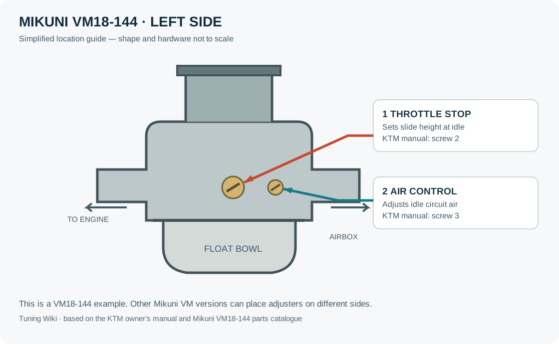
- Mikuni VM round-slide, models covered by the manual: Mikuni VM manual, PDF page 2, shows the exploded view and identifies air screw 29 and idle adjusting screw 32. The orientation and model table on PDF page 3 show that the sides can differ between models.
- Keihin FCR-MX: Keihin FCR-MX exploded view identifies the pilot screw as item 32 and the idle-speed screw as item 90. The parts drawing is an assembly view, not a universal guide to all FCR versions.
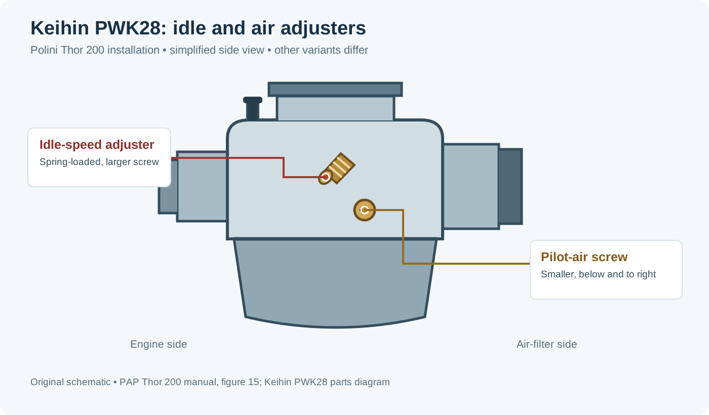
- Keihin PWK28: Sudco PWK28 exploded view, catalogue page 134 identifies the air-adjust screw as item 17 and the idle adjuster as item 29. See also Sudco's slide-carburettor tuning guide, which distinguishes the FCR fuel screw from the air screw on PWK, CR, PJ and PE examples.
- Edelbrock Performer and Thunder Series AVS/AVS2: Edelbrock installation instructions, page 3, figure 1, label the idle speed screw and both idle mixture screws. Check the model and application notes in the instructions.
- Amal Concentric as used on 1969–70 Norton Commando: Norton parts catalogue, carburettor section page C10, shows an exploded diagram and identifies the throttle-stop screw as 26 and pilot-air screw as 27. Other Amal types and applications may differ.
- Motorcraft 2700/7200 variable-venturi: the Ford training manual, figure 2 and figure 16, illustrates adjustment locations and curb-idle arrangements. The 7200 feedback system and the 2700 differ; match the unit and service procedure.
- Fish-type swinging-arm design: US patent 3,291,464, figures 1 and 2, depicts one Fish-type design and identifies the throttle idle-stop screw as 32. This is a patent example rather than a universal Reece Fish service diagram.
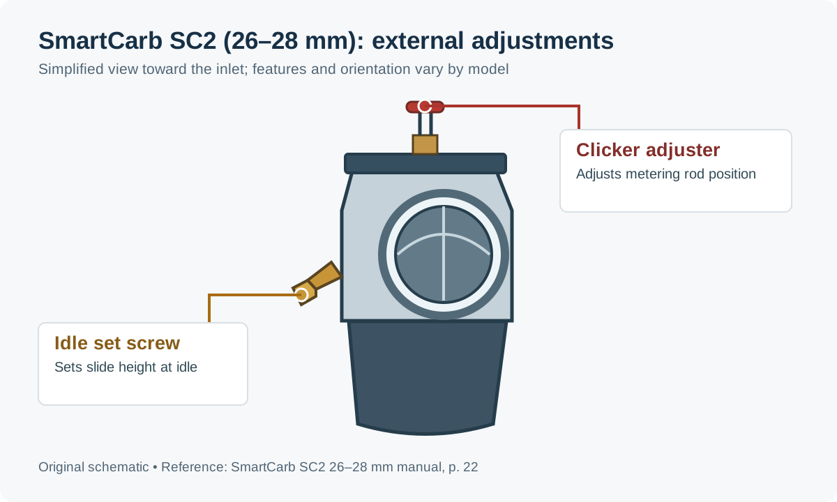
- SmartCarb SC2 26–28 mm metering-rod carburettor: the manufacturer’s manual, page 22, labels the metering-rod clicker adjuster and idle set screw. Consult the matching manual for other sizes and generations.
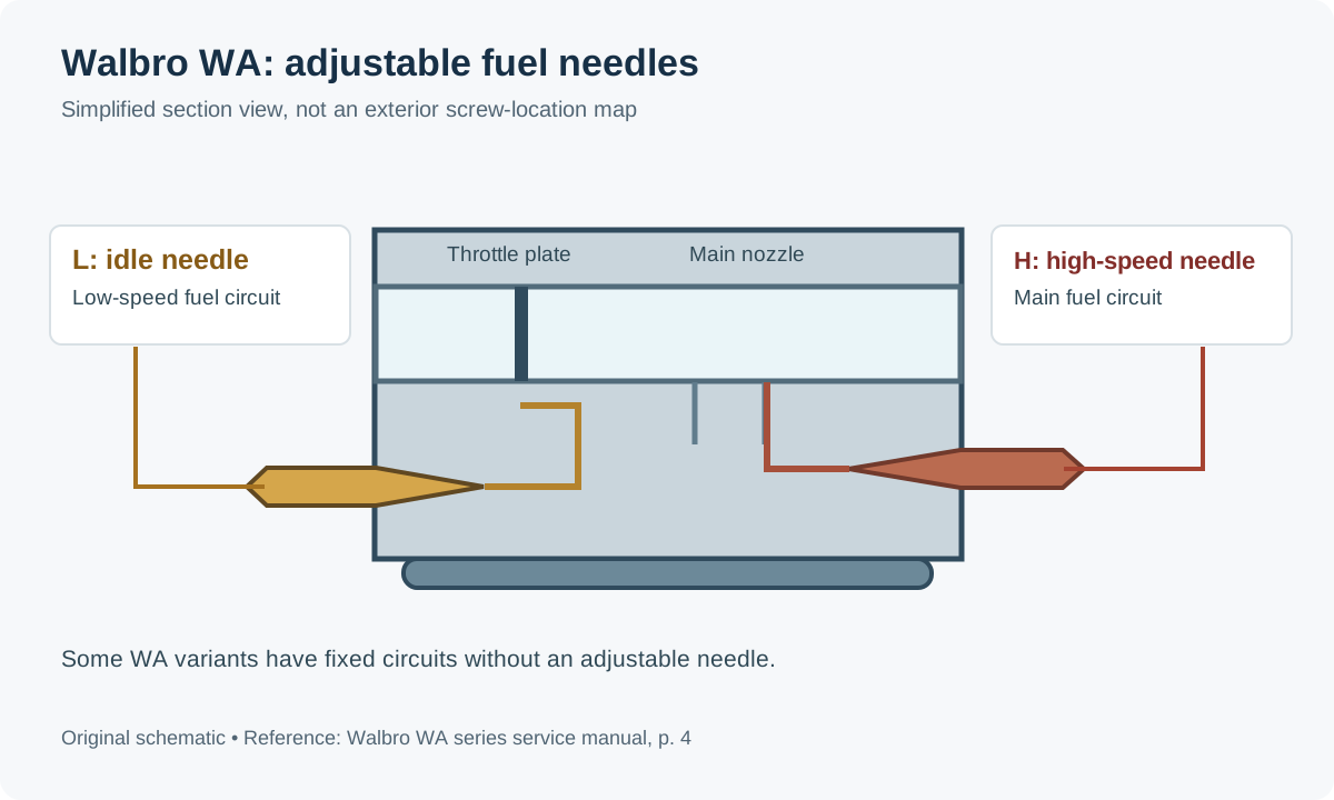
- Walbro WA-series diaphragm carburettor: Walbro WA-series manual, page 4, shows a labelled cross-section with idle and high-speed needles; some versions have fixed circuits without an adjustment needle.
- Bendix-Stromberg PS-series aircraft pressure carburettor: the Bendix service manual, figure 9, identifies the idle-speed and idle-mixture adjustments. Aircraft installation and carburettor part-list requirements determine the applicable maintenance instructions.
- IMPCO 425 gaseous-fuel mixer: IMPCO master catalogue, printed page 107, shows an exploded Model 425 drawing; item 21 is the idle-adjust screw. Designs and tamper-resistant provisions vary. The Model 55 bulletin separately labels the idle and power adjustments for the 90-degree air-horn version.
- Zenith-Stromberg CD, CDS and CD-2S: Zenith’s numbered diagrams and guide identify the throttle stop screw as 3, fast-idle stop as 4, and jet-orifice adjustment as 13 on the illustrated versions. Later and emissions variants can differ; see Zenith-Stromberg CD carburettors.
- Zenith IZ, 24-T2 and 30 VIG: see the Zenith guide for links to model-specific labelled exterior diagrams.

Edelbrock Performer / Thunder AVS idle controls

Walbro WA fuel adjustment needles
IMPCO Model 55 mixer adjusters

SmartCarb SC2 adjustment locations
Related pages
- Carburettors (section overview)
- Weber carburettor tuning: DCOE, IDF, IDA and DGV
- Dellorto DHLA carburettors: specs and tuning
- Holley 4150 and 4160 carburettors: identification and tuning
- SU carburettor troubleshooting, servicing and mixture adjustment
- SU H-type, Thermo and AED servicing
- Zenith-Stromberg CD carburettors: operation, setup and tuning
- Zenith carburettor operation, jetting and servicing
- Carburettor types and layouts
- Carburettor makes and model families
- Carburettor fuel circuits and metering
- Carburettor synchronisation, faults and rebuilds
- Carburettor fuel supply: pumps, regulators and vapour lock
- Turbocharging and supercharging a carburettor engine
Sources
- The SU Carburetter and Fuel Pump Workshop Manual. The SU Carburetter Company, 1958; independent PDF copy. Expanding choke, single jet and tapered needle, and cold-start jet movement. Accessed 2026-11-11.
- Weber Carburettors DCOE Manual. Progression, main jet, emulsion tube and air corrector operation.
- Holley Model 4160 Manual, Holley 4150 Ultra XP Manual, Holley Power Enrichment System, and Secondary Diaphragm Spring Kit.
- Holley, Inside Your Holley Carburetor, tech library, undated. Cruise-vacuum power-valve rule. Accessed 2026-11-19.
- Holley / Weiand Supercharger Technical Information. Boost-referenced carburation.
- Edelbrock Carburetor Owner's Manual and Tuning Guide. Metering rod and spring tuning.
- Mikuni VM Super Tuning Manual and Sudco Keihin Carburetor Tuning Guide.