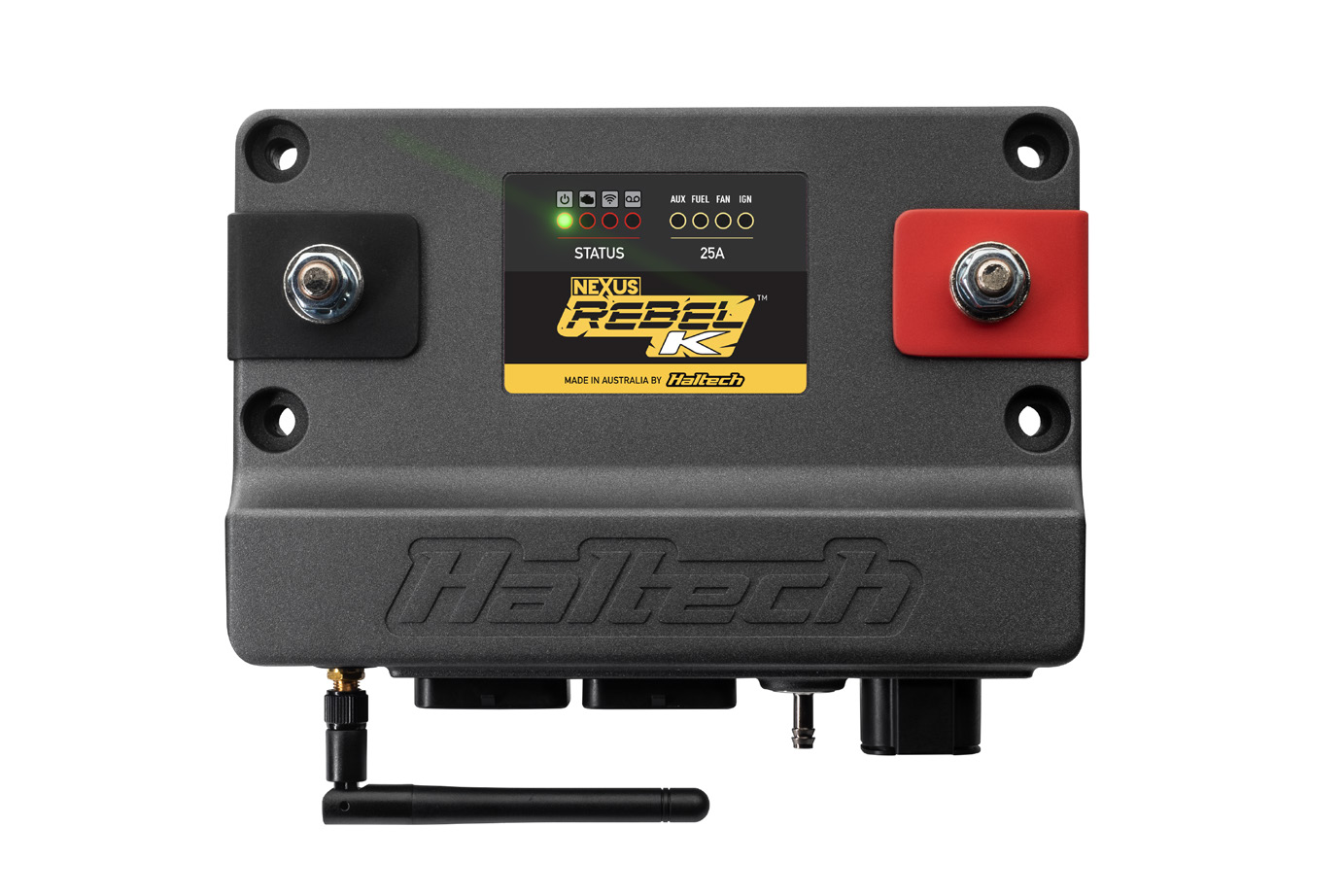
Haltech Nexus Rebel K: A Honda K-series application ECU and terminated-harness package. Haltech's HT-186402 main-harness listing names K20A, K24A and K24Z engines and says injector, throttle and transmission sub-harnesses are separate. Factory K-series coil connectors are integrated into that main harness. Manufacturer information.
Identification and connection
Record ECU model, serial, hardware revision, firmware and loom part number before choosing wiring. Confirm the exact engine, crank sensor, throttle type and injector sub-harness. The source provides a wiring diagram for the HT-186402 harness; use its engine-specific connector information rather than a universal Haltech pinout. Model-specific manual or diagram.
Software and related models
Use the manufacturer's model-appropriate software and documentation. Configuration and available outputs depend on exact hardware and the intended installation. See the manufacturer model index for related systems.
Manufacturer ECU and terminated-harness connections
From Haltech's Rebel K terminated harness guide, pages 4–5 and 14–15. The schedules identify the functions and wire colours of this specific terminated harness; they do not assert that unused harness positions are absent from every ECU configuration. Check the connector face and exact application. Connector A is keyway type 1, C is keyway type 2, and E is the four-way DTP.
ECU connector A: 34-way
| Pin | Harness function | Wire colour |
|---|---|---|
| A1 | Injector 1 | Blue |
| A2 | Injector 2 | Blue/Black |
| A3 | Injector 3 | Blue/Brown |
| A4 | Injector 4 | Blue/Red |
| A5 | Unused | No connection |
| A6 | Unused | No connection |
| A7 | Unused | No connection |
| A8 | Unused | No connection |
| A9 | DPO 1 (Cabin) | Violet/Black |
| A10 | Power ground output | Black |
| A11 | Power ground output | Black |
| A12 | DPO 2 (Cabin) | Violet/Brown |
| A13 | Ignition switch input | Pink |
| A14 | DPO 3 (Cabin) | Violet/Red |
| A15 | DPO 4 (Throttle) | Violet/Orange |
| A16 | DPO 5 (Boost) | Violet/Yellow |
| A17 | Tacho Output | Violet/Green |
| A18 | Transmission Supply | Pink/Red |
| A19 | HBO 1 (Throttle) | Brown/Black |
| A20 | HBO 2 (Throttle) | Brown/Red |
| A21 | VTEC | Brown/Green |
| A22 | VTC | Brown/Pink |
| A23 | CAN 1 High | White |
| A24 | CAN 1 Low | Blue |
| A25 | CAN Supply | Pink/Brown |
| A26 | Constant power (12V) | Red |
| A27 | Ignition 1 | Yellow/Black |
| A28 | Ignition 2 | Yellow/Red |
| A29 | Ignition 3 | Yellow/Orange |
| A30 | Ignition 4 | Yellow/Green |
| A31 | Unused | No connection |
| A32 | Unused | No connection |
| A33 | Unused | No connection |
| A34 | Unused | No connection |
ECU connector C: 34-way
| Pin | Harness function | Wire colour |
|---|---|---|
| C1 | Trigger + (Crank) | Yellow |
| C2 | Unused | No connection |
| C3 | Home + (Exhaust Cam) | Yellow |
| C4 | Unused | No connection |
| C5 | SPI 1 (Cabin) | Gray/Brown |
| C6 | SPI 2 (Spare) | Gray/Red |
| C7 | Intake Cam | Yellow |
| C8 | Flex Fuel | Gray/Yellow |
| C9 | Unused | No connection |
| C10 | AVI 1 (Cabin) | White |
| C11 | AVI 2 (Cabin) | White/Yellow |
| C12 | Fuel pressure | White/Gray |
| C13 | Oil pressure | White/Violet |
| C14 | MAP | White/Green |
| C15 | Throttle TPS | White/Orange |
| C16 | Throttle TPS 2 | White/Black |
| C17 | Cabin APP 1 | White/Brown |
| C18 | Cabin APP 2 | White/Red |
| C19 | SPI 5 (Spare) | Gray/Pink |
| C20 | Transmission VSS | Gray/L.Green |
| C21 | CAN 2 High | White |
| C22 | CAN 2 Low | Blue |
| C23 | Knock 1 | Black/Blue |
| C24 | Unused | No connection |
| C25 | 5V sensor supply | Orange |
| C26 | Sensor ground | Black/White |
| C27 | Coolant temp | L.Green |
| C28 | Air temp | L.Green/Black |
| C29 | WBI 1 Heater + | Gray |
| C30 | WBI 1 Common | Yellow |
| C31 | WBI 1 Pump | Red |
| C32 | WBI 1 Nernst | Black |
| C33 | WBI 1 Heater - | White |
| C34 | WBI 1 Cal | Green |
ECU connector E: 4-way
| Pin | Harness function | Wire colour |
|---|---|---|
| E1 | AX25+ (Starter) | Red/Blue |
| E2 | Fuel pump | Red/Yellow |
| E3 | Fan | Red/Orange |
| E4 | Switched 12V | Red/Green |
The following additional schedules are the harness-side APP and throttle breakout connector views in the guide, not the ECU connector pins. Pin 21 of the separate cabin connector is the brake signal.
APP pedal connector: 6-way
| Pin | Harness function | Wire colour |
|---|---|---|
| 1 | Sensor ground | Black/White |
| 2 | APP 1 | White/Brown |
| 3 | +5 V | Orange |
| 4 | +5 V | Orange |
| 5 | APP 2 | White/Red |
| 6 | Sensor ground | Black/White |
Throttle breakout connector: 12-way
| Pin | Harness function | Wire colour |
|---|---|---|
| 1 | Unused | No connection |
| 2 | Unused | No connection |
| 3 | HBO 1 | Brown/Black |
| 4 | HBO 2 | Brown/Red |
| 5 | Sensor ground | Black/White |
| 6 | +5 V | Orange |
| 7 | AVI 6 | White/Orange |
| 8 | AVI 7 | White/Black |
| 9 | Brake | Light green/Brown |
| 10 | Switched 12 V | Red/Green |
| 11 | DPO 4 | Violet/Orange |
| 12 | Unused | No connection |