MaxxECU RACE — Eight-cylinder sequential ECU with eight peak-and-hold injectors, electronic throttle, knock inputs and eight thermocouple inputs. MaxxECU product information.
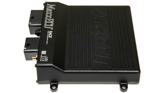
Model identification and capabilities
The manufacturer lists eight ignition outputs, nine low-driving auxiliary outputs, two 12 V driving outputs and four motor outputs. Built-in features include a 400 kPa MAP sensor, wideband lambda controller and two knock inputs. Up to twelve cylinders can be controlled with wasted-spark ignition, depending on configuration. Manufacturer specification; MaxxECU model comparison.
| Sequential cylinders, maximum | 8 |
|---|---|
| Injector outputs | 8 peak-and-hold |
| Ignition outputs | 8 |
| Configuration | MTune; check the release appropriate to the ECU and hardware revision |
Identification and installation
This is the original RACE, not GEN2 RACE. Use the model and hardware revision to select the wiring diagram; the manufacturer identifies RACE H2O as a separate water-protected version.
Record the model label, serial number, hardware revision, firmware, connector keying and loom. Outputs can be assigned or share functions; supported functions also depend on available I/O and software configuration. The figure in the comparison is a controller capability, not proof of compatibility with a particular engine or vehicle.
Connector and pinout
Complete 48-way connector 1 positions from the manufacturer’s model-specific column. A dash in the source is shown as not assigned. Consult the drawing for orientation and the remaining connectors. Exact wiring and connector reference.
| Position | Manufacturer function | Notes |
|---|---|---|
| A1 | GPO 5 | |
| A2 | IGN 1 | |
| A3 | IGN 2 | |
| A4 | GPO 8/TACHO | 660ohm pullup |
| B1 | GPO 6 | |
| B2 | IGN 3 | |
| B3 | IGN 4 | |
| B4 | GPO 1 | |
| C1 | GPO 7 | |
| C2 | IGN 5 | |
| C3 | IGN 6 | |
| C4 | GPO 2 | |
| D1 | WBO2 Heater- | |
| D2 | IGN 7 | |
| D3 | IGN 8 | |
| D4 | GPO 3 | |
| E1 | CAN H | |
| E2 | CAN L | |
| E3 | GND Shield | |
| E4 | GPO 4 | |
| F1 | CLT | |
| F2 | IAT | |
| F3 | WBO2 VREF | |
| F4 | WBO2 VS | |
| G1 | +5V sensor supply | (peak 0.5A, max 150mA) |
| G2 | TPS/AIN | |
| G3 | WBO2 IP | |
| G4 | WBO2 RCAL | |
| H1 | Sensor GND | |
| H2 | Trigger GND | |
| H3 | TRIGGER | |
| H4 | HOME | |
| J1 | AIN 1 (Temperature) | |
| J2 | AIN 2 (Temperature) | |
| J3 | AIN 3 (0-5V) | |
| J4 | AIN 4 (0-5V) | |
| K1 | INJ 1 | |
| K2 | INJ 2 | |
| K3 | DIN/VR 1 | |
| K4 | DIN/VR 2 | |
| L1 | INJ 8 | |
| L2 | INJ 7 | |
| L3 | INJ 6 | |
| L4 | Engine GND | |
| M1 | INJ 3 | |
| M2 | INJ 4 | |
| M3 | INJ 5 | |
| M4 | +12V ECU power supply |
RACE connector 2
From the manufacturer’s GEN1 connector reference; check connector view, hardware revision and current ratings in the original.
| Position | Manufacturer function | Notes |
|---|---|---|
| A1 | egt 5+ | |
| A2 | egt 6+ | |
| A3 | egt 7+ | |
| A4 | egt 8+ | |
| B1 | egt 5- | |
| B2 | egt 6- | |
| B3 | egt 7- | |
| B4 | egt 8- | |
| C1 | EGT 1 + | |
| C2 | EGT 2+ | |
| C3 | EGT 3+ | |
| C4 | EGT 4+ | |
| D1 | EGT 1- | |
| D2 | EGT 2- | |
| D3 | EGT 3- | |
| D4 | EGT 4- | |
| E1 | KNOCK GND | |
| E2 | Knock 1 | |
| E3 | knock 2 | |
| E4 | AIN 6 (0-5v) | |
| F1 | ain 7 (0-5v) | |
| F2 | ain 8(0-5V) | |
| F3 | din/vr 4 | |
| F4 | din/vr5 | |
| G1 | gpo 15(+12v) | |
| G2 | gpo 16 (+12v) | |
| G3 | ain 5 (0-5V) | |
| G4 | eNGINE GROUND | |
| H1 | mOTOR 2+ | |
| H2 | mOTOR 1- | |
| H3 | mOTOR 2- | |
| H4 | mOTOR 1+ |
Consult the full diagram for wiring, grounds, supply fuses, driver limits, connector orientation and remaining positions. Sensor grounds and power grounds have different purposes; follow the matching manual.
Software and further documents
- MaxxECU RACE: product information
- Model wiring and pinout reference
- MTune, quick-start guides and revision-specific wiring downloads
- MaxxECU family overview
Sources reviewed 17 November 2026.