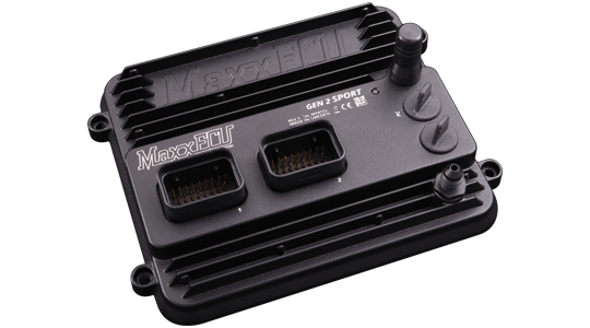
MaxxECU GEN2 SPORT is a six-cylinder sequential standalone engine-management ECU in the GEN2 family. It is distinct from the earlier SPORT and from GEN2 TRACK and RACE. MaxxECU GEN2 SPORT product information.
Identification and capabilities
The manufacturer lists six peak-and-hold injector/general-purpose outputs and six selectable ignition/general-purpose outputs, with seven additional low-side outputs and two H-bridge outputs. It supports up to six sequential cylinders or twelve with wasted spark. Four pulse inputs accept VR or digital signals, and twelve analogue inputs have selectable pull-ups.
The ECU includes a 550 kPa absolute MAP sensor, one wideband controller supporting Bosch LSU 5.2, 4.9 and 4.2, and two knock-sensor inputs. The manufacturer specifies USB-C, Wi-Fi, Bluetooth and CAN; 4 GB internal logging; and an integrated three-axis accelerometer. Configuration is through MTune; MDash provides mobile connectivity. Manufacturer specification and product image.
Installation and revision
MX1 and MX2 are the relevant GEN2 SPORT connectors. Pin functions in MX2 differ from the RACE/TRACK column. Record the hardware revision, firmware, part number and actual loom; package contents vary. Check driver and fuse ratings and verify each signal and load against the manufacturer documentation before wiring.
Connector pinouts
The tables follow the SPORT column in MaxxECU's GEN2 wiring reference; empty model-specific cells inherit the shared function. Consult the original drawings for connector orientation and electrical limits.
Connector MX1
From the manufacturer's GEN2 SPORT connector reference; establish the connector view and check wiring and current limits in the original.
| Pin | Function | Note |
|---|---|---|
| 1 | Ignition 1 | |
| 2 | Ignition 2 | |
| 3 | Ignition 3 | |
| 4 | Ignition 4 | |
| 5 | GP out 1 (GND) | |
| 6 | GP out 2 (GND) | |
| 7 | GP out 3 (GND) | |
| 8 | GP out 4 (GND) | |
| 9 | Engine gnd | To engine cylinder head. |
| 10 | Digital/VR 1 (PULSE) SIGNAL + | |
| 11 | Digital/VR 1 (PULSE) SIGNAL - | |
| 12 | Digital/VR 1 (PULSE) POWER SUPPLY | |
| 13 | Digital/VR 1 (PULSE) SHIELD | |
| 14 | SENSOR GND | Must NOT be connected to engine GND |
| 15 | CAN L | |
| 16 | CAN H | |
| 17 | GP out 5 (GND) | |
| 18 | Digital/VR 2 (PULSE) SIGNAL + | |
| 19 | Digital/VR 2 (PULSE) SIGNAL - | |
| 20 | Digital/VR 2 (PULSE) POWER SUPPLY | |
| 21 | Digital/VR 2 (PULSE) SHIELD | |
| 22 | 5V power supply | |
| 23 | Digital/VR 3 (PULSE) SIGNAL + | |
| 24 | Digital/VR 4 (PULSE) SIGNAL + | |
| 25 | 12V supply 1 | Main ECU supply. |
| 26 | AIN 1 | |
| 27 | AIN 2 | |
| 28 | AIN 3 | |
| 29 | AIN 4 | |
| 30 | AIN 5 | |
| 31 | INJECTOR 1 | |
| 32 | INJECTOR 2 | |
| 33 | INJECTOR 3 | |
| 34 | INJECTOR 4 |
Connector MX2
From the manufacturer's GEN2 SPORT connector reference; establish the connector view and check wiring and current limits in the original.
| Pin | Function | Note |
|---|---|---|
| 1 | Ignition 5 | |
| 2 | Ignition 6 | |
| 3 | GP out 6 (GND) | |
| 4 | AIN 6 | |
| 5 | AIN 7 | |
| 6 | AIN 8 | |
| 7 | GP out 13 (H-BRIDGE 1) | |
| 8 | GP out 14 (H-BRIDGE 1) | |
| 9 | Engine gnd | To engine cylinder head. |
| 10 | WBO2 Sensor 1 VS | |
| 11 | WBO2 Sensor 1 COM/VREF | |
| 12 | GP OUT 7 / WBO2 Sensor 1 H- | |
| 13 | AIN 9 | |
| 14 | AIN 10 | |
| 15 | AIN 11 | |
| 16 | AIN 12 | |
| 17 | Not available | |
| 18 | WBO2 sensor 1 RCAL | |
| 19 | WBO2 sensor 1 IP | |
| 20 | 12V WBO2 sensor 1 H+ | |
| 21 | WBO2 sensor 1 SHIELD | |
| 22 | Not available | |
| 23 | Not available | |
| 24 | 12V supply 3 | Used for ignition key or to power the internal RTC |
| 25 | 12V supply 2 | Must be wired if 12V driving output exceeds 10A |
| 26 | KNOCK1 SHIELD | |
| 27 | KNOCK 1- | |
| 28 | KNOCK 1+ | |
| 29 | KNOCK 2 SHIELD | |
| 30 | KNOCK 2- | |
| 31 | KNOCK 2+ | |
| 32 | Not available | |
| 33 | INJECTOR 5 | |
| 34 | INJECTOR 6 |
Further documentation
- MaxxECU GEN2 SPORT product page
- MaxxECU GEN2 pinout and output limitations
- MTune, wiring and manuals
- MaxxECU manufacturer overview
Sources reviewed 17 November 2026.