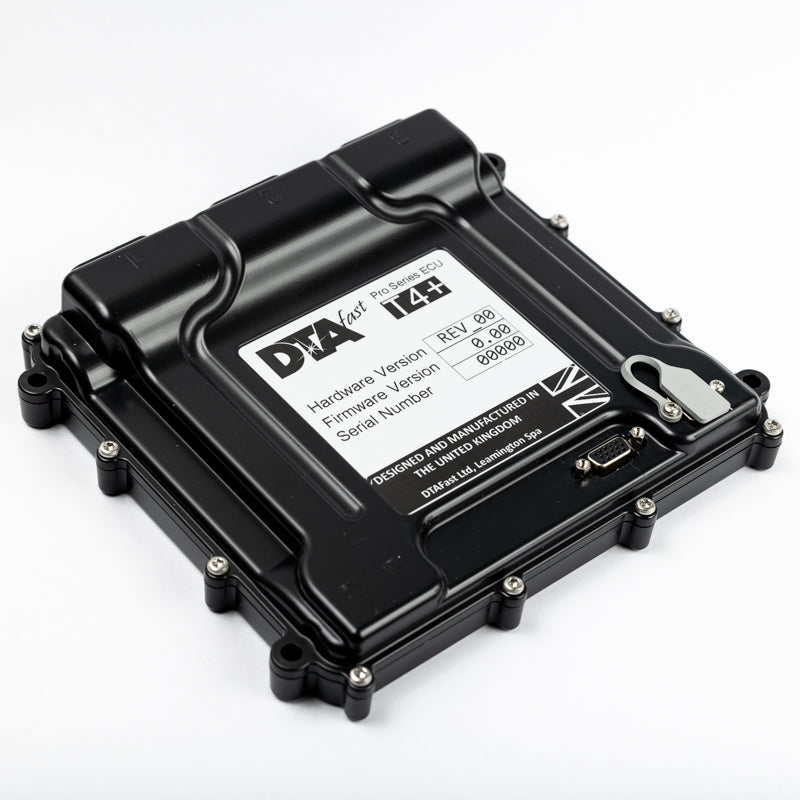
DTAFast T4+ is a programmable T-series engine ECU. Four cylinders fully sequential or six and eight semi-sequential. One drive-by-wire throttle, one knock sensor and one variable cam control. Manufacturer specification and product photographs.
Control and software
DTAFast describes configurable inputs and outputs, Bosch wideband control, on-board logging, and a trigger oscilloscope in T-Series PC software. Capabilities, logging rates and pin usage vary by unit and firmware; confirm the exact installation and ECU specification. Product details.
Connector pinout and wiring
Use the T4+ manufacturer wiring diagram for numbered connector cavities, diagram orientation, switched and permanent supplies, grounds, actuators, sensors and hardware-revision notes. Outputs can be configurable: confirm assignments and limits in both the diagram and actual calibration. The similarly named non-plus ECU has its own separate pinout.
Complete connector pin assignments
These pin positions and labels are from the DTAFast T4-PLUS wiring diagram, shown from the pin-insertion side. A dash means no function is shown in the drawing. Verify the ECU version, electrical limits and configured functions before wiring.
Connector 1 — pinout version 1.04
| Pin | Function in manufacturer diagram |
|---|---|
| 1 | Coil 3 |
| 2 | - |
| 3 | PWM 3 |
| 4 | PWM 2 |
| 5 | PWM 1 |
| 6 | Motor 1 + |
| 7 | Motor 1 - |
| 8 | - |
| 9 | Injector 1 |
| 10 | Coil 1 |
| 11 | - |
| 12 | - |
| 13 | Power Ground 1 |
| 14 | Power Ground 2 |
| 15 | - |
| 16 | - |
| 17 | Injector 2 |
| 18 | Coil 2 |
| 19 | - |
| 20 | - |
| 21 | - |
| 22 | - |
| 23 | - |
| 24 | - |
| 25 | Injector 4 |
| 26 | Coil 4 |
| 27 | - |
| 28 | - |
| 29 | - |
| 30 | - |
| 31 | Ignition 12v In |
| 32 | - |
| 33 | - |
| 34 | Injector 3 |
Connector 2 — pinout version 1.04
| Pin | Function in manufacturer diagram |
|---|---|
| 1 | Analogue 2 |
| 2 | Wheel 1 |
| 3 | Analogue 10 |
| 4 | Digital 1 |
| 5 | Analogue 3 |
| 6 | Analogue 4 |
| 7 | Thermistor 1 |
| 8 | - |
| 9 | 5v Output |
| 10 | Analogue 1 |
| 11 | - |
| 12 | Crank Sensor |
| 13 | - |
| 14 | Digital 4 |
| 15 | Digital 5 |
| 16 | Analogue 11 |
| 17 | Thermistor 3 |
| 18 | - |
| 19 | Analogue 6 |
| 20 | - |
| 21 | Sensor Ground |
| 22 | Cam 1 |
| 23 | - |
| 24 | 5v Output |
| 25 | Thermistor 2 |
| 26 | CAN High |
| 27 | - |
| 28 | CAN Low |
| 29 | - |
| 30 | - |
| 31 | - |
| 32 | - |
| 33 | Sensor Ground |
| 34 | Analogue 9 |
Connector 3 — pinout version 1.04
| Pin | Function in manufacturer diagram |
|---|---|
| 1 | - |
| 2 | - |
| 3 | - |
| 4 | - |
| 5 | - |
| 6 | - |
| 7 | Lambda 1 Pump Current |
| 8 | Lambda 1 VGND |
| 9 | Lambda 1 Heater Negative |
| 10 | PWM 8 |
| 11 | Lambda 1 Trim Resistor |
| 12 | Lambda 1 Nernst Voltage |
| 13 | - |
| 14 | - |
| 15 | - |
| 16 | - |
| 17 | Analogue 7 |
| 18 | Analogue 8 |
| 19 | - |
| 20 | - |
| 21 | - |
| 22 | PWM 4 |
| 23 | PWM 5 |
| 24 | PWM 6 |
| 25 | PWM 7 |
| 26 | Permanent 12v |
| 27 | Permanent 12v |
| 28 | - |
| 29 | - |
| 30 | - |
| 31 | Knock 1 |
| 32 | - |
| 33 | - |
| 34 | - |
Identification
Record the exact model suffix, hardware revision, firmware, serial and harness before modifying wiring or calibration. Obtain software and manuals from DTAFast and see the DTAFast family reference for related models and legacy controllers.