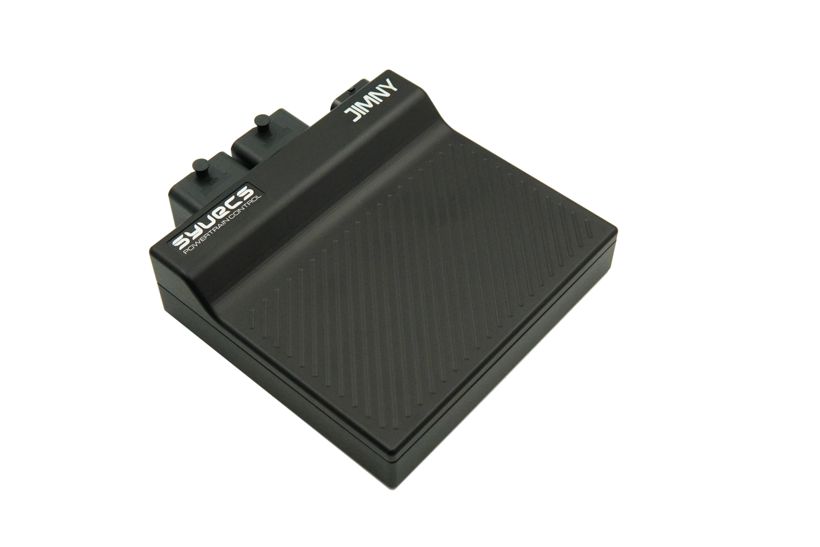
Model and vehicle application
Syvecs lists this vehicle-specific standalone or plug-in ECU kit as Suzuki Jimny Sierra JB74 2018 onward, with product code S7i- JimnyDF. The product page and its stated vehicle, model and transmission details define this particular application; confirm market, model year, engine, ECU connector and transmission against Syvecs before ordering.
This entry describes the dedicated vehicle kit. It is distinct from the generic wire-in ECU: a plug-in kit can use application-specific adaptor wiring, a carrier, additional modules and an application calibration. The listed hardware or supported equipment can vary by revision.
Wiring and pinout
Syvecs Suzuki Jimny Sierra JB74 2018 onward installation and wiring document. Follow the connector orientation, application-specific tables, installation notes and hardware revision in this document. Do not transfer assignments from another vehicle merely because the underlying ECU family is similar. The link was checked to return a PDF.
For other variants and manual revisions consult the manufacturer's vehicle-specific manual index. Available spare inputs and outputs can be used only within their electrical limits and with a matching calibration.
Calibration and service
Use the correct Syvecs software, firmware and base calibration for the exact vehicle and installed hardware. The Syvecs software portal and firmware archive provide manufacturer support. A base map is a starting point and needs checking against the actual engine, injectors, sensors and modifications.
Sources
- Syvecs Suzuki Jimny Sierra JB74 2018 onward product listing and application
- Manufacturer kit installation and pinout manual
- Syvecs plug-in kit support index
Additional 26-way I/O connector
From the Syvecs Suzuki Jimny installation guide. The guide calls the 26-way connector a front connector during installation but a rear connector in its pinout section; identify it physically from the manufacturer diagram. This is the documented additional connector only; the table is not a complete factory vehicle connector pinout. Confirm the connector view and hardware configuration in the guide.
| Pin | Function |
|---|---|
| 1 | Ground |
| 2 | Fuel 6 output |
| 3 | Fuel 5 output |
| 4 | Fuel 13 output |
| 5 | Fuel 14 output — wastegate solenoid |
| 6 | Fuel 16 output |
| 7 | Vbat — 12 V supply for ECU bench power, or NTK lambda heater supply |
| 8 | Fuel 8 output |
| 9 | Lam1v — NTK L2H2 grey wire |
| 10 | Lam1i — NTK L2H2 white wire |
| 11 | LamGnd — NTK L2H2 black wire |
| 12 | RS232 RX |
| 13 | RS232 TX |
| 14 | Not connected |
| 15 | AN13 — air charge temperature input |
| 16 | AN3 — MAP sensor input |
| 17 | +5 V regulated output |
| 18 | EGT1 − |
| 19 | EGT1 + |
| 20 | Analogue sensor ground |
| 21 | CAN2 H |
| 22 | CAN2 L |
| 23 | LAN RX− — orange/white |
| 24 | LAN RX+ — white/orange |
| 25 | LAN TX− — green/white |
| 26 | LAN TX+ — white/green |