The Holley 4150 and 4160 are the most widely used aftermarket four-barrel carburettors for V8 engines. Both share the same 5.16 × 5.625 in flange, main body layout and externally adjustable float bowls. They differ at the secondary end: the 4150 carries a screw-in-jet metering block at both ends, while the 4160 uses a thin secondary metering plate with fixed drillings. Holley's own instruction sheets show that most driveability problems come from fuel pressure, float level, vacuum leaks and idle set-up rather than from the out-of-box jetting, which Holley describes as "extremely close".

Identification
- List number: on 2300, 4150, 4160, 4165 and 4175 models the list number is stamped on the right side of the choke air horn, with a date code of up to four digits below it. On choke-less 4150 HP race bodies it is stamped into the main body behind the throttle linkage (Holley support page; not directly verified). The list number, not the casting, identifies the calibration.
- 4150 vs 4160: a 4150 is slightly longer because it has jets at both ends. A 4160's secondary calibration is changed by swapping the whole plate; Holley's conversion kit 34-6 replaces the plate with a block, and its instruction sheet converts plate numbers to equivalent jets (for example a #9 plate is equivalent to a pair of 67 jets).
- Double pumper vs vacuum secondary: "double pumper" means mechanically opened secondaries plus a second accelerator pump. Holley describes these as intended for lightweight manual cars, or automatics with a high-stall converter and low gearing. Vacuum-secondary carburettors open the secondaries according to airflow and suit a wider range of vehicles.
- Bowls: fuel bowls use either a centre-pivot ("centre-hung") or side-pivot ("side-hung") float, both with an externally adjustable needle and seat.
- Current families (Holley product literature): Ultra Street Avenger (vacuum secondary), Ultra Double Pumper (mechanical, four-corner idle, sight glasses), 4150 HP (choke-less race body with replaceable air bleeds and a quick-change secondary cover), Ultra XP (billet blocks with replaceable idle feed restrictions, emulsion bleeds and PVCR, plus an idle bypass valve) and the diecast Brawler range.
- Not a 4150: the 4500 Dominator uses a larger 5.375 × 5.375 in flange and is not interchangeable.
Where the calibration parts are
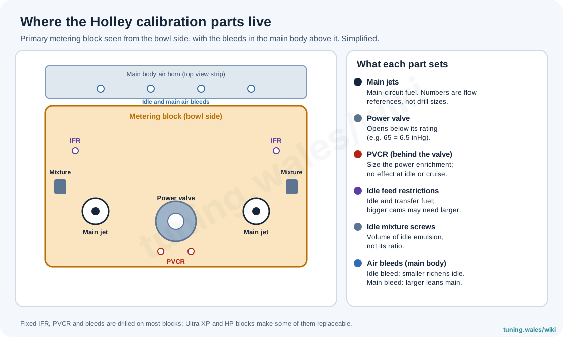
- Main jets: Holley jets are broached, flow-tested and stamped by flow rate. The number is a reference, not a drill size, and Holley says a jet must never be drilled. One jet number is roughly 4.5 % change in flow; Holley advises changing two sizes at a time and treats a need for 8–10 sizes as a sign of a fuel-supply fault or the wrong carburettor.
- Power valve: held shut by manifold vacuum and opened by its spring when vacuum falls below its rating. A "65" valve opens below 6.5 inHg. See fuel circuits and metering for how power enrichment works.
- PVCR (power valve channel restrictions): the two drillings behind the power valve. Their size, not the valve itself, sets how much fuel is added under load; they have no effect at idle or part throttle.
- Idle feed restrictions (IFR) and idle air bleeds: together set the idle and transfer calibration. A smaller idle air bleed richens, a larger one leans. Long-duration, high-overlap camshafts usually need a larger IFR. The mixture screws change the volume of idle emulsion delivered, not its air-fuel ratio.
- Main air bleeds and emulsion bleeds: a larger main air bleed leans the whole main circuit. Holley warns against moving bleeds more than six sizes from the as-shipped size, and describes emulsion-bleed tuning on HP and XP blocks as best done on a dynamometer.
Float level and fuel pressure
Set fuel pressure first: Holley states that any change in pressure changes the float level. The published figures differ slightly between Holley documents but all fall between 5 and 7.5 psi. The 4150 HP and race sheets give 5 psi minimum and 7.5 psi maximum and warn of "severe fuel control problems" above 7.5 psi; the 0-1850S manual gives 5–7 psi; the double-pumper sheet asks for 7 psi at idle and at least 4 psi at maximum rpm. Holley's own carburettor regulators ship set at about 7 psi. See carburettor fuel supply for pumps, regulators and filters.
Wet float level (engine running, vehicle level): remove the sight plug, loosen the lock screw and turn the adjusting nut (clockwise lowers, anticlockwise raises) until fuel sits at the bottom of the sight-hole threads with a slight trickle when the car is rocked. Ultra models with sight glasses should read mid-glass. Before first start, Holley advises filling the bowls in stages (cranking 10 s on a mechanical pump, or switching an electric pump on and off) to avoid power-valve damage and a cocked needle.
| Float type (dry setting, bowl inverted) | Primary | Secondary |
|---|---|---|
| Brass or nitrophyl, side-hung | 7/64 in at toe | 13/64 in at heel |
| Duracon, centre-hung | 5/16 in | 3/8 in |
| Duracon, side-hung | 7/32 in | 5/16 in |
Dry settings are a starting point only; the wet sight-plug check is the final setting (Holley float adjustment guidelines).
Idle set-up and the transfer slot
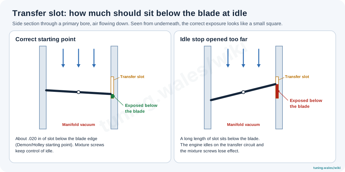
The transfer slot is cut in the bore just above the closed primary throttle blade. If the idle-speed screw is wound in to make a large-camshaft engine idle, too much slot ends up below the blade edge. The engine then idles on the transfer circuit, the mixture screws lose effect and the car stumbles off idle. Demon (a Holley brand) gives a starting point of about 0.020 in of slot showing below the blade when viewed from underneath, which looks like a small square; Holley's support guidance gives no more than 0.025–0.030 in. On engines idling below about 1,000 rpm the secondary blades should sit at the bottom of their slot. If the engine needs more air to idle than this allows, the cure is more idle air from another route (secondary-blade opening, an idle bypass on Ultra XP models, or drilled blades on some race carburettors), not more primary throttle.
Mixture procedure (Holley tuning sheets): start with each mixture screw 1.5–2 turns out. With a vacuum gauge on full manifold vacuum, turn the screws in equal 1/8-turn steps for the highest vacuum, then reset idle speed. Without a gauge, set for highest rpm. Automatics are set in Drive. On four-corner-idle carburettors all four screws are moved by equal amounts.
Choosing the power valve
Holley's documents give two rules that can give different answers:
- Instruction-sheet rule: a 65 valve suits engines idling at 12 inHg or more; below that, use about half the idle vacuum, with 45 or 35 for radical automatics idling near 6 inHg.
- Tech-library rule ("Inside Your Holley Carburetor"): choose a valve about 2 inHg below warm idle vacuum (in gear for automatics) on race camshafts, or about 2 inHg below the lowest steady-cruise vacuum on street engines.
The aim of both is the same: the valve must stay shut at idle and steady cruise, or the engine runs rich at idle and cruise. On a street car the cruise-vacuum rule is the more direct test of that, and a wideband at steady cruise confirms it. Since 1992 Holley performance carburettors have a check-ball system in the throttle body that closes on a backfire to protect the power-valve diaphragm; older carburettors without it can rupture the valve on an intake backfire (faults and rebuilds).
Main jetting, altitude and temperature
Holley calibrates at sea level and 70 °F and states the out-of-box jetting rarely needs more than four sizes richer, except on large-plenum and tunnel-ram manifolds (three to five sizes). Holley's correction is one jet size leaner per 2,000 ft of altitude and one size richer per 35 °F drop in air temperature. Tune primary jets at steady part-load first, then secondary jets at sustained full throttle, confirming each with a wideband lambda sensor or on a dynamometer.
Secondaries
Vacuum-secondary opening is set by the diaphragm spring. A stiffer spring opens the secondaries later. Holley's spring kit 20-13 gives the following measured opening points, without an air cleaner (an air cleaner makes them open earlier):
| Spring colour | Relative rate | 350 cu in: start / fully open (rpm) | 402 cu in: start / fully open (rpm) |
|---|---|---|---|
| White | Lightest | Not given | |
| Short yellow | Lighter | 1,620 / 5,680 | 1,410 / 4,960 |
| Yellow | Light | 1,635 / 5,750 | 1,420 / 5,020 |
| Purple | Medium-light | 1,915 / 6,950 | 1,680 / 6,050 |
| Plain | Medium | 2,240 / 8,160 | 1,960 / 7,130 |
| Brown | Medium-heavy | 2,710 / 8,750 | 2,380 / 7,650 |
| Black | Heavy | 2,720 / not fully open | 2,390 / not fully open |
Holley's procedure is to fit lighter springs until a flat spot appears, then go back one step stiffer, testing with the air cleaner fitted. A bog at 2,000–3,000 rpm calls for a heavier spring. Clipping a spring makes it stiffer, not softer. If the lightest spring still does not open the secondaries fully, the carburettor is too large for the engine. The quick-change cover (20-59) allows a spring change without removing the housing. Vacuum secondaries must never be forced open with a screw: they have no pump shot, and the result is a lean bog or backfire. Mechanical secondaries normally begin to open at about 40° of primary rotation.
Accelerator pump
- Volume: the standard pump is 30 cc; the 50 cc conversion is 20-11. Holley pairs the 50 cc pump with discharge nozzles of #37 and larger, and its own tuning blog says a street car rarely needs one.
- Nozzles ("shooters"): stamped in thousandths of an inch (35 = 0.035 in), from 0.025 to 0.052 in; use the hollow screw from 0.040 in up. Change three sizes at a time. A hesitation followed by pick-up, or a backfire on acceleration, calls for a larger nozzle.
- Override clearance: at full throttle with the pump lever fully compressed, leave 0.015 in between the adjusting nut and the lever, and check the pump moves at the slightest throttle opening. Re-check after every cam change.
- Pump cams (kit 20-12): Holley's general tuning sheet says hole #1 starts the shot early and suits 600–700 rpm idles, while #2 and #3 delay it for idles around 1,000 rpm and above. The Ultra XP sheet describes the holes differently (#1 moderate initial and greater total delivery, #2 greater initial and less total). Follow the sheet for the specific carburettor.
Sizing
Holley's sizing formula is CFM = cu in × maximum rpm ÷ 3,456 × volumetric efficiency, with VE about 80 % for a mild engine, 85 % for a performance engine and 95 % for a race engine. Holley's example: 300 cu in at 8,000 rpm and 85 % VE needs about 595 cfm, so a 600 cfm carburettor. Holley advises choosing a rating equal to or slightly below the result ("when in doubt, select a smaller carburetor"); mechanical-secondary carburettors are sized from a separate chart of minimum full-throttle rpm (converter stall on automatics). Oversized carburettors reduce booster signal and hurt low-speed response; see carburettor tuning, jetting and setup.
Common faults
| Symptom | Usual cause on a Holley |
|---|---|
| Black smoke at idle and cruise, mixture screws ineffective | Ruptured power valve (older carburettors without the check-ball), or loose bowl screws: Holley specifies 25–30 in-lb |
| Rough idle after fitting | Vacuum leak at a torn flange gasket, unplugged port or intake gasket; base nuts over-tightened (Holley: 60–80 in-lb criss-cross) and base warped |
| Flooding | Dirt in the needle and seat (Holley treats an inline filter as mandatory), or fuel pressure above 7–7.5 psi |
| Fuel dripping from boosters after hot shutdown | Percolation: fuel boiling in the bowl. Fit a phenolic spacer or heat shield; Holley support suggests a float level about 1/8 in below the sight hole (not directly verified) |
| Erratic metering with an air cleaner fitted | Less than 3/4 in between the vent tubes and the air-cleaner lid |
Not established
- Holley's official pump-cam colour and lift chart: vendor lists of colour order contradict each other and are not reproduced here.
- The full 4160 plate-to-jet equivalence table and the needle-and-seat stamp-to-size mapping.
Related pages
- Carburettor tuning, jetting and setup
- Carburettor fuel circuits and metering
- Carburettor fuel supply: pumps, regulators and vapour lock
- Turbocharging and supercharging a carburettor engine
- Holley Sniper EFI (throttle-body replacement)
Sources
- Holley, Rebuild and Adjustment Manual, 199R10013, rev. 24 Jan 2014 (retailer-hosted copy). List-number location. Accessed 2026-11-19.
- Holley, 0-80457S/0-1850S Installation, Tuning and Adjustment Manual, 199R11081, undated (retailer-hosted). Fuel pressure, float level, filling bowls, torque figures, vacuum leaks. Accessed 2026-11-19.
- Holley, High Performance Tuning Instructions, 199R7849-2, rev. 20 Jan 2014. Power valve, nozzles, pump cam, mixture procedure. Accessed 2026-11-19.
- Holley, Performance Carburetor Installation and Adjustment Instructions (double pumper), undated. Pressure, bowl screws, vent-tube clearance. Accessed 2026-11-19.
- Holley, Inside Your Holley Carburetor, tech library, undated. Jet steps, power-valve selection, pump volume, check-ball system, mechanical secondaries. Accessed 2026-11-19.
- Holley, General Guidelines for Adjusting Floats, undated. Dry float settings. Accessed 2026-11-19.
- Holley, Model 4160 to 4150 Conversion Kit, 199R8110, rev. 13 Apr 2015. Accessed 2026-11-19.
- Holley, Model 4150 Aluminum Ultra XP Series, 199R12389, 4 Apr 2022. PVCR, IFR, bleeds, altitude and temperature correction, pump cam positions. Accessed 2026-11-19.
- Holley, Model 4150 HP Series, 199R10016-2, rev. 30 Sep 2016. Fuel pressure, idle procedure. Accessed 2026-11-19.
- Demon Carburetion (Holley), Aluminum Carburetors Instruction Manual, LIT732, rev. 29 Mar 2019. Transfer-slot exposure. Accessed 2026-11-19.
- Holley, Secondary Diaphragm Spring Kit 20-13, 199R8219-2, rev. 21 Sep 2012 (retailer-hosted). Spring table and procedure. Accessed 2026-11-19.
- Holley, How to Select the Right Carburetor Size, tech library, undated. CFM formula. Accessed 2026-11-19.
- Holley, Aluminum Carburetors Update flyer, undated. Product families. Accessed 2026-11-19.
- Holley, Carburetor Technical Support and Motor Life blog pages, undated. Read from search-index excerpts only because the pages refused automated access; used only where marked. Accessed 2026-11-19.