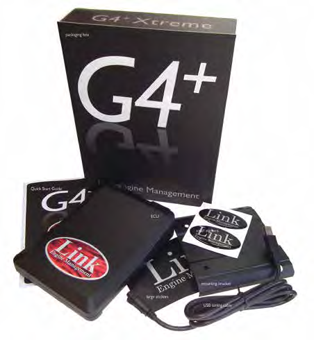
Link G4+ Force GDI is a programmable G4+ wire-in engine-management ECU. A direct-injection controller with a dedicated high-pressure pump control output. Its guide documents GDI injector pairing by firing order and a distinctive electronic-throttle circuit; do not apply an ordinary port-injection pinout. Link G4+ Force GDI quick-start guide.
Model identification and I/O
| Item | Documented details |
|---|---|
| ECU family | G4+ |
| Outputs | Four direct-injection negative channels with two shared positive feeds |
| Programming | PCLink version matched to ECU generation and firmware |
| Connector and loom | See the exact-model guide, including connector keys, wire-side orientation and optional functions |
The manufacturer guidance and wiring identify the hardware; driver counts do not establish injector electrical compatibility or imply all multiplexed pins can be used at the same time.
Model-specific pinout and installation
The G4+ Force GDI quick-start guide provides the connector diagrams and installer I/O table. Refer to that version for numbered cavities, wire colours, supply, grounds, driver and sensor connection notes. Loom wire-side and ECU header views are identified on the diagram; do not transfer a pin number from another generation.
Software and further sources
Download software, firmware and full installation help from Link's download centre; identify the ECU generation and installed firmware before choosing a PCLink package. The legacy software list separates G5, G4X and G4+ compatibility. See also Link standalone ECUs.
Force GDI connector assignments
The Link G4+ Force GDI quick-start guide, pages 4–5, shows these positions looking into the wire side of each loom connector or into the ECU header. Follow its keyed A and B connector drawings and numbering. On serial numbers 32384 and higher A18 is Aux 10 and A26 is Aux 8; for earlier units the guide identifies A18 as Aux 4 and A26 as blank. B18 Aux 4 is unavailable when electronic throttle is used; B27 and B28 can be configured as CAN 2 or digital inputs. Check the specific serial number and configuration.
A connector
| Pin | Function | Wire colour |
|---|---|---|
| A1 | +14 V battery | Brown/orange |
| A2 | Injector 1+ | Brown/red |
| A3 | Injector 2+ | Brown |
| A4 | GDI pump | Brown/black |
| A5 | +14 V | Red |
| A6 | +8 V | Red/white |
| A7 | Shield/ground | Green |
| A8 | Trigger 1 | Black |
| A9 | Trigger 2 | Red |
| A10 | Ignition 4 | Blue/orange |
| A11 | Ignition 3 | Blue/red |
| A12 | Ignition 2 | Blue/brown |
| A13 | Ignition 1 | Blue |
| A14 | Analog volt 4 | White/black |
| A15 | Temperature 1 | Yellow |
| A16 | Temperature 2 | Yellow/brown |
| A17 | Analog volt 1 | Yellow/blue |
| A18 | Auxiliary 10 / Auxiliary 4, see serial number note | Orange |
| A19 | Auxiliary 3 | Orange/red |
| A20 | Auxiliary 2 | Orange/brown |
| A21 | Auxiliary 1 | Orange/black |
| A22 | Analog volt 2 | White/brown |
| A23 | DI 3 | Grey/red |
| A24 | Ground out | Green |
| A25 | Ground | Black |
| A26 | Auxiliary 8 / blank, see serial number note | Orange/purple |
| A27 | Auxiliary 7 | Orange/blue |
| A28 | Auxiliary 6 | Orange/green |
| A29 | Auxiliary 5 | Orange/yellow |
| A30 | DI 1 | Grey/black |
| A31 | DI 2 | Grey/brown |
| A32 | +5 V | Red/blue |
| A33 | Analog volt 3 | Yellow/black |
| A34 | Ground | Black |
B connector
| Pin | Function | Wire colour |
|---|---|---|
| B1 | Injector 2B | Brown/purple |
| B2 | Injector 2A | Brown/blue |
| B3 | Injector 1B | Brown/green |
| B4 | Injector 1A | Brown/yellow |
| B5 | +14 V Aux 9/10 | Red |
| B6 | Temperature 3 | Yellow/red |
| B7 | Temperature 4 | Yellow/orange |
| B8 | Knock 2 | White |
| B9 | Knock 1 | White |
| B10 | Heater | Blue/purple |
| B11 | RE | Blue/black |
| B12 | IPE | Blue/green |
| B13 | APE | Blue/yellow |
| B14 | MES | Blue/white |
| B15 | Analog volt 6 | White/red |
| B16 | Analog volt 7 | White/orange |
| B17 | Shield/ground | Green |
| B18 | Auxiliary 4 / electronic throttle positive | Purple/white |
| B19 | DI 6 | Grey/green |
| B20 | DI 5 | Grey/yellow |
| B21 | DI 4 | Grey/orange |
| B22 | Ground out | Green |
| B23 | Analog volt 8 | White/yellow |
| B24 | Analog volt 9 | White/green |
| B25 | Ground | Black |
| B26 | Auxiliary 9 / electronic throttle negative | Purple |
| B27 | DI 10 / CAN 2 high | Grey/purple |
| B28 | DI 9 / CAN 2 low | Grey/white |
| B29 | DI 8 | Grey |
| B30 | DI 7 | Grey/blue |
| B31 | Analog volt 10 | White/blue |
| B32 | Analog volt 11 | White |
| B33 | Analog volt 5 | Yellow/green |
| B34 | Ground | Black |
For the high-voltage GDI drivers, shared positive supplies, pump control and electronic throttle, follow the model-specific wiring and firing-order examples in the same guide; the conventional port-injection arrangement is not interchangeable.
Link G4+ family illustration