The Adaptronic eMod009 is an application-specific plug-in programmable engine-management ECU. Haltech's surviving Adaptronic downloads archive identifies the application as Mazda RX-7 FC Series 4. The part number identifies a family of applications, not an unconditional guarantee of vehicle compatibility. Haltech Adaptronic downloads archive.
Application and installation
Identify the vehicle, engine, connector and wiring variation before installation. Plug-in installation can still require additional sensor and actuator wiring, and tuning to suit the specific engine. The manufacturer archive provides the Adaptronic plug-in ECU startup guide and EUGENE tuning software.
Model-specific pinout
In the eMod009 section of the manufacturer download archive, find: RX7_S4_Pinout.zip. Open the matching vehicle-specific diagram; connector or pin functions cannot safely be inferred from a different eMod or a different application. The archive also lists the following basemap resource: eMod009_Basemap_RX7S4_factoryIgnition_factoryInjectors_v001.ecu.
RX-7 Series 4 FC Turbo connector assignments
From the manufacturer’s eMod009 RX7 S4 pinout archive, applicable to the 1985–1988 13B single-turbo RX-7 FC. The connector drawing is viewed looking into the ECU. These are Adaptronic assignments, which may differ from the factory function. Connector 4 positions A–F depend on the installed expansion module; NC means no connection as described by the manufacturer. The manufacturer notes that removing the airflow meter requires additional wiring to control the fuel pump. Confirm the configuration, wiring and source diagram before installation.
| Position | Adaptronic function / notes |
|---|---|
| 1A | CAN H |
| 1B | CAN L |
| 1C | Injector output 8 (air bypass) |
| 1D | CAS 3 (flex fuel possible) |
| 1E | Digital input 4 (aircon request) |
| 1F | Ignition output 7 (aircon relay) |
| 1G | Digital input 2 (neutral switch) |
| 1H | Knock input |
| 1I | Ignition output 2 (direct-fire L2) |
| 1J | Ignition output 5 (spare) |
| 1K | Ignition output 8 (shift light) |
| 1L | Digital input 1 (clutch switch) |
| 1M | NC |
| 1N | CAS 2 (2-tooth trigger) |
| 1O | VSS input |
| 1P | Sensor ground |
| 1Q | Sensor ground |
| 1R | Digital input 3 (knock input) |
| 1S | Auxiliary output 1 (port air valve) |
| 1T | CAS 1 (24-tooth trigger) |
| 1U | Ignition output 4 (igniter address / trailing 2 in direct fire) |
| 1V | Ignition output 1 (leading / leading 1 in direct fire) |
| 1W | Ignition output 6 (heat hazard light) |
| 1X | Ignition output 3 (trailing / trailing 1 in direct fire) |
| 2A | TPS 5 V supply |
| 2B | External IMAP (optional) |
| 2C | Sensor ground |
| 2D | O2 input 1 (0–5 V analogue) |
| 2E | External 0–5 V input 1 |
| 2F | External 0–5 V input 2 |
| 2G | TPS 1 input |
| 2H | Tacho output |
| 2I | Coolant temperature |
| 2J | Oil temperature |
| 2K | Auxiliary output 3 (boost valve) |
| 2L | Manifold air temperature |
| 2M | Auxiliary output 4 (pressure regulator control) |
| 2N | Injector output 5 (EGR valve) |
| 2O | Injector output 6 (switching valve) |
| 2P | Injector output 7 (relief valve) |
| 2Q | Auxiliary output 2 (idle) |
| 2R | Power ground |
| 3A | Power ground |
| 3B | NC |
| 3C | Injector output 2 (rear primary) |
| 3D | Fuel pump control output (optional) |
| 3E | Injector output 1 (front primary) |
| 3F | Injector output 4 (rear secondary) |
| 3G | Power ground |
| 3H | Injector output 3 (front secondary) |
| 3I | 12 V power input |
| 3J | NC |
| 4A | Module 1; function depends on expansion fitted |
| 4B | Module 1; function depends on expansion fitted |
| 4C | Module 1; function depends on expansion fitted |
| 4D | Module 1; function depends on expansion fitted |
| 4E | Module 1; function depends on expansion fitted |
| 4F | Module 1; function depends on expansion fitted |
| 4G | NC |
| 4H | Oil pressure |
| 4I | Fuel temperature |
| 4J | Fuel pressure |
| 4K | TPS 2 input (spare 0–5 V) |
| 4L | External EMAP |
| 4M | Servo input (0–5 V, default electronic oil-metering pump position) |
| 4N | O2 input 2 (spare 0–5 V) |
| 4O | 5 V output |
| 4P | Sensor ground |
Documentation limits
Complete channel counts and additional variants have not been independently verified for this exact model. Haltech's Adaptronic notice records the end of Adaptronic operations in 2022; use the archived documentation and confirm present support before purchasing a used ECU.
Manufacturer connector diagram and ECU photograph
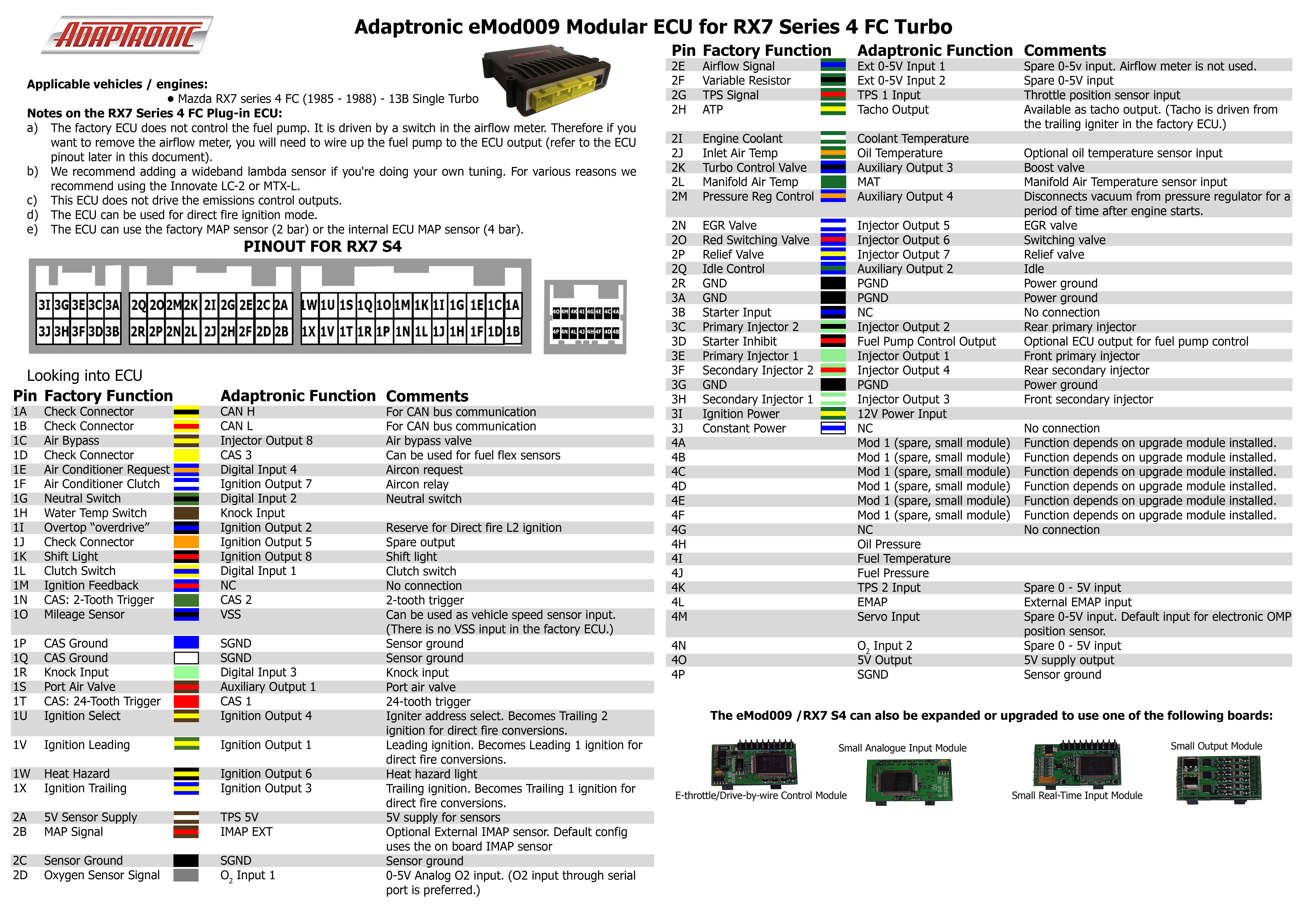
Connector pinout
A structured pinout with redrawn pin-index diagrams for all four connectors (68 positions) is on Adaptronic eMod009 connector pinout. Diagram redrawn by Tuning Wiki from the Adaptronic RX7_S4_Pinout archive (manufacturer documentation).