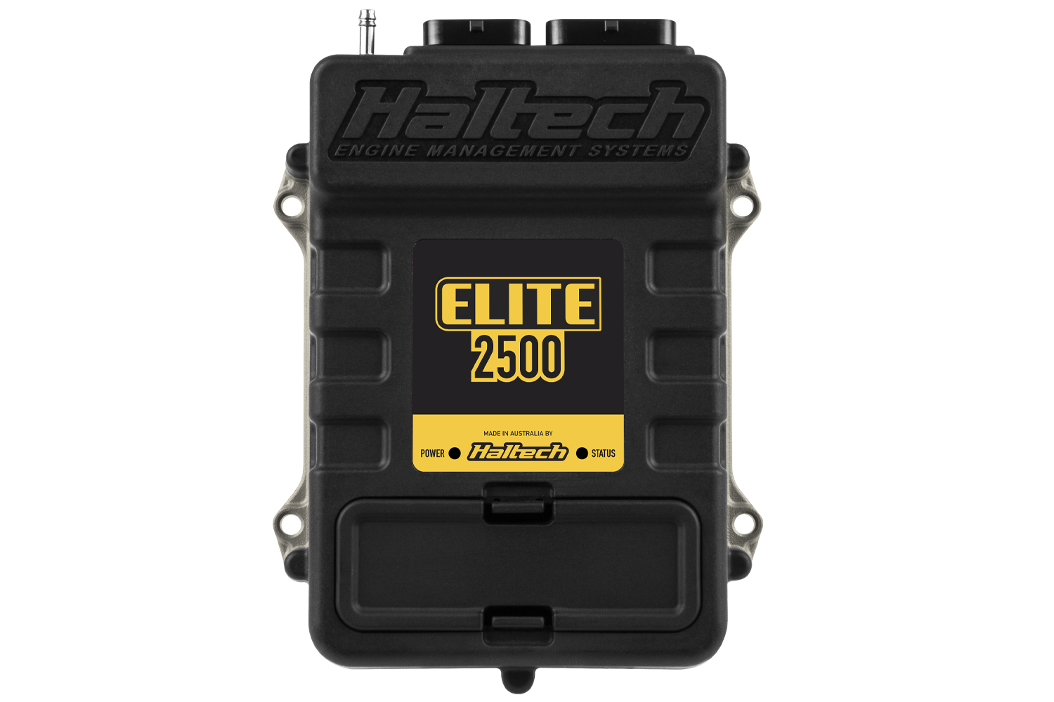
Haltech Elite 2500 is a programmable engine-management ECU in Haltech's Elite family. Eight injector and ignition channels, 10 analogue inputs and half-bridge outputs for stepper or electronic throttle. Haltech universal comparison.
Identification and I/O
| Item | Manufacturer comparison |
|---|---|
| Injector channels | 8, peak-and-hold |
| Ignition channels | 8 |
| Digital pulsed outputs | 5 |
| MAP sensor | 4 bar internal |
| Tuning software | ESP for Elite firmware 2.xx; NSP for Elite firmware 3.xx; verify installed firmware |
Counts do not imply that all functions are available simultaneously: driver allocation, injector impedance, ignition type, firmware and calibration must suit the installation.
Pinout and wiring
Use the manufacturer wiring diagrams and select the Elite 2500 ECU and actual harness or part number. Drawings for other models and plug-in adaptors are not a substitute for the identified unit. Verify connector orientation, power and grounds, current limits and output assignment before connection.
Manufacturer connector tables
The following are the manufacturer-listed 34-way and 26-way connector assignments for the Elite 2500, including the loom wire-colour abbreviations used by Haltech. A dash is retained where the manufacturer does not list an assignment. Confirm ECU part number, connector view, software configuration and electrical limits against the linked original diagrams; do not transfer assignments from another model. On the 34-way plug, the ECU injector-power input is required for ECU operation.
34-way connector
Haltech Elite 2500 34-pin manufacturer pinout
| Pin | Wire colour code | Function in source |
|---|---|---|
| 1 | V/BR | DPO 2 |
| 2 | O/Y | AVI 4 |
| 3 | Y/B | IGN 1 |
| 4 | Y/R | IGN 2 |
| 5 | Y/O | IGN 3 |
| 6 | Y/G | IGN 4 |
| 7 | Y/BR | IGN 5 |
| 8 | Y/L | IGN 6 |
| 9 | O | +5V DC |
| 10 | B | BATTERY GROUND |
| 11 | B | BATTERY GROUND |
| 12 | O/W | +8V DC |
| 13 | P | 12V IGNITION INPUT |
| 14 | W | AVI 10 ( TPS ) |
| 15 | Y | AVI 9 ( MAP ) |
| 16 | O/B | AVI 2 |
| 17 | O/R | AVI 3 |
| 18 | V/B | DPO 1 |
| 19 | L | INJ 1 |
| 20 | L/B | INJ 2 |
| 21 | L/BR | INJ 3 |
| 22 | L/R | INJ 4 |
| 23 | V/R | DPO 3 |
| 24 | B/Y | DPO 5 ( FUEL PUMP TRIGGER) |
| 25 | B/R | DPO 6 ( ECR OUT) |
| 26 | R/L | ECU INJECTOR POWER INPUT (REQUIRED CONNECTION FOR ECU TO OPERATE) |
| 27 | L/O | INJ 5 |
| 28 | L/Y | INJ 6 |
| 29 | L/G | INJ 7 |
| 30 | L/V | INJ 8 |
| 31 | G | STEPPER 1 P1 / DPO |
| 32 | G/B | STEPPER 1 P2 / DPO |
| 33 | G/BR | STEPPER 1 P3 / DPO |
| 34 | G/R | STEPPER 1 P4 / DPO |
26-way connector
Haltech Elite 2500 26-pin manufacturer pinout
| Pin | Wire colour code | Function in source |
|---|---|---|
| 1 | Y (SHD) | CRANK (TRIGGER) ( + ) |
| 2 | Y (SHD) | CAM (HOME) ( + ) |
| 3 | GY | AVI 7 (AIR TEMP) |
| 4 | V | AVI 8 (COOLANT TEMP) |
| 5 | G (SHD) | CRANK (TRIGGER) ( - ) |
| 6 | G (SHD) | CAM (HOME) ( - ) |
| 7 | GY/R (SHD) | SPI 4 |
| 8 | GY (SHD) | SPI 1 |
| 9 | GY/B (SHD) | SPI 2 |
| 10 | GY/BR (SHD) | SPI 3 |
| 11 | R/W | +13.8V ECU SUPPLY (ECU POWER) |
| 12 | GY/O (SHD) | AVI 6 (O2 INPUT 1) |
| 13 | GY/Y (SHD) | AVI 1 (O2 INPUT 2 ) |
| 14 | B/W | SIGNAL GROUND |
| 15 | B/W | SIGNAL GROUND |
| 16 | B/W | SIGNAL GROUND |
| 17 | Y/V | IGN 7 |
| 18 | Y/GY | IGN 8 |
| 19 | V/O | DPO 4 |
| 20 | O/G | AVI 5 |
| 21 | GY/G | KNOCK 1 |
| 22 | GY/L | KNOCK 2 |
| 23 | W | CAN H |
| 24 | L | CAN L |
| 25 | BR/B | DBW 1 / DPO |
| 26 | BR/R | DBW 2 / DPO |
Software and further information
Download the matching software and firmware through Haltech downloads. For family context and other models see Haltech standalone ECUs. Compare the label, serial, connectors and map backup before replacing a controller.
Haltech groups the Elite 2500 basic, premium and race-expansion harness wiring diagrams with its Elite 1500/2500/REM downloads. Select the exact 2500 harness entry on that page.