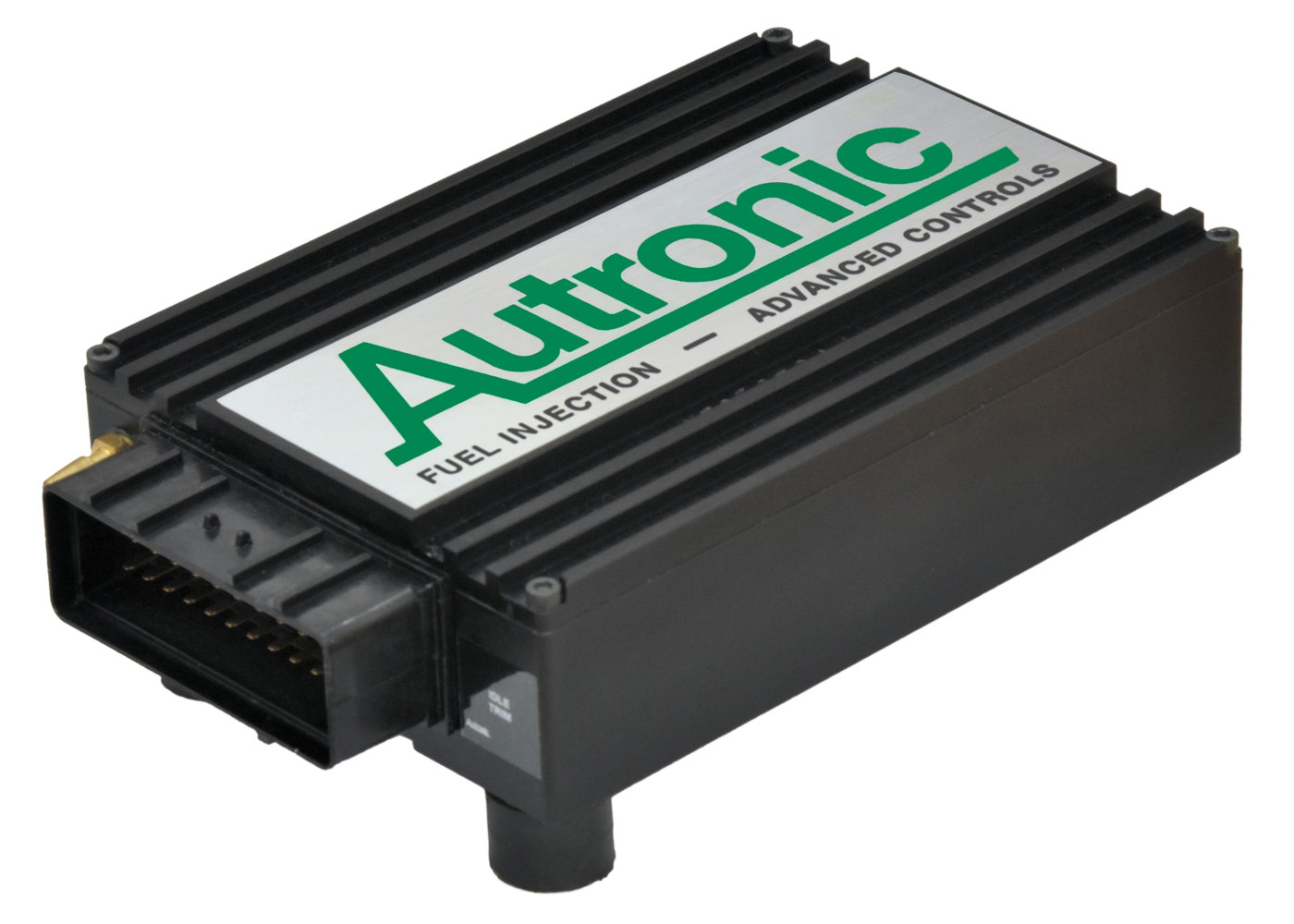
Autronic SMCMR is a standalone or earlier programmable engine-management system. Marine-labelled SMC version; the manufacturer provides firmware and multiple early/current loom wiring guides. Model-specific information.
Identification and features
Record the ECU label, model, part number, hardware revision, firmware, configured injectors, ignition hardware and loom before comparing systems. Some outputs can be reassigned; hardware, software, current limits and engine-specific options determine what is actually available.
Processor
Autronic's SMCMR product page (manufacturer documentation) gives a 16-bit Intel CPU running at 16 MHz. The exact part number is not stated in the sources checked.
Engine applications
The SMCMR is the marine-oriented SMC in a sealable billet aluminium case, for ski-boat and marine racing as well as high-performance motorsport. Per Autronic it suits high-output supercharged or turbocharged engines with multi-point or centre-point injection, two-stroke engines and engines with uneven firing sequences. Selectable cylinder counts are 1 to 8, 10, 12, 14 and 16 (full sequential for 2 to 8; semi-sequential above 8). Hardware: eight injector drivers (selectable 4 A/1 A or 2 A/0.5 A), four open-collector ignition outputs without dwell control on the standard unit, one auxiliary output, fuel pump control, RS232 serial, and a 36-way AMP connector. No engine codes are listed.
Wiring and pinout
Consult the Autronic SMCMR wiring and documentation source and identify the exact connector face, part and version. Do not apply wiring from a similarly named model. If an exact drawing is unavailable for the unit at hand, obtain it from the manufacturer or supplier before making connections.
J1 connector: manufacturer loom drawings
The 36-position J1 table, from Autronic's Type 1 pre-1996 diagram, revision 003 and universal Type 2 Rev C diagram, revision 005 (both linked from the manufacturer's SMCMR page), is on the Autronic SMC connector pinout page with a redrawn pin-index diagram (diagram redrawn by Tuning Wiki). The Type 1 loom is specified only for ECUs made before 1996; the Type 2 drawing states it suits all SMC ECUs. Check the unit date, loom type, firmware and options before wiring.
| J1 pin | Type 1 pre-1996 drawing | Type 2 Rev C universal drawing | Drawing wire colour |
|---|---|---|---|
| 1 | Injector 7 output | Injector 7 output | Grey/blue |
| 2 | Injector 6 output | Injector 6 output | Blue/black |
| 3 | Injector 4 output | Injector 4 output | Green/white |
| 4 | Injector 2 output | Injector 2 output | Orange/black |
| 5 | Injector 1 output | Injector 1 output | Pink/black |
| 6 | Coolant temperature input | Coolant temperature input | Pink |
| 7 | O2 input | O2 input | Blue |
| 8 | Reference trigger input | Reference trigger input | Green |
| 9 | Serial RX | Serial RX | Purple |
| 10 | Ignition 4 output | Ignition 4 output | Not specified |
| 11 | Ignition 2 output | Ignition 2 output | Not specified |
| 12 | Auxiliary output | Auxiliary output | Grey |
| 13 | ECU +12 V supply | ECU +12 V supply | Red |
| 14 | Injector 8 output | Injector 8 output | Blue/red |
| 15 | Injector 5 output | Injector 5 output | Green/yellow |
| 16 | Injector 3 output | Injector 3 output | Blue/white |
| 17 | Sensor ground | Sensor ground | Black |
| 18 | Throttle position input | Throttle position input | Orange |
| 19 | Throttle position supply | Throttle position supply | Red/white |
| 20 | Trigger supply | Trigger supply | Red/black |
| 21 | Serial I/O ground | Switch input | Black / green-orange respectively |
| 22 | Ignition 3 output | Ignition 3 output | Not specified |
| 23 | Diagnostic output (optional connection) | Diagnostic output (optional connection) | Not specified |
| 24 | Fuel pump output | Fuel pump output | Blue |
| 25 | +12 V / pump relay supply | +12 V / pump relay supply | Red |
| 26 | +12 V / auxiliary output supply | +12 V / auxiliary output supply | Pink/yellow |
| 27 | ECU ground | ECU ground | Black |
| 28 | ECU ground | ECU ground | Black |
| 29 | Ignition switch input | Ignition switch input | Red |
| 30 | Intake air temperature input | Intake air temperature input | White |
| 31 | Trigger ground | Trigger ground | Black |
| 32 | Cylinder pulse trigger input | Cylinder pulse trigger input | Yellow |
| 33 | Serial TX | Serial TX | Orange |
| 34 | Not labelled on Type 1 drawing | Serial I/O ground | Not specified / black respectively |
| 35 | Ignition 1 output | Ignition 1 output | Pink/white |
| 36 | Ignition output ground | Ignition output ground | Not specified |
Further information
Sources
- Autronic SMCMR product page. Manufacturer. Accessed 19 November 2026.
- SMC loom, universal Type 2 Rev C, revision 005. Manufacturer drawing. Accessed 19 November 2026.