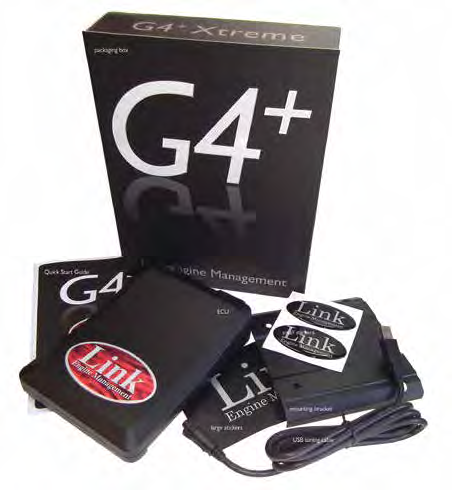
Link G4+ Kurofune is a documented G4+ Link engine-management designation. The manufacturer catalogue describes Kurofune as an adapter-loom-oriented G4+ ECU with eight injection and eight ignition drives, four analogue outputs, 10 digital and nine analogue inputs, and differential trigger inputs. It lists a 64-pin connector; its separate CAN connection is shown in the guide. Identification source.
Identification and software
Record the complete model and revision label, board identifiers, installed firmware, connector configuration and any adapter loom. Similar Link model names occur in later generations. Use the manufacturer's legacy PCLink compatibility table and seek Link support if the appropriate package is unclear.
Model-specific wiring
The Kurofune quick-start guide includes its connector and installer I/O tables. Its connector arrangements are not interchangeable by appearance alone.
See Link standalone ECUs for related models and generation distinctions.
Manufacturer connector assignments
The Link G4+ Kurofune quick-start guide identifies three keyed connectors A, B and C carrying positions 1–64, plus an eight-position XS/J connector. The source diagrams show their key and orientation; confirm these on the actual connectors. The differential trigger pairs and analog outputs require the model-specific wiring arrangements in that guide.
A connector
| Pin | Function |
|---|---|
| 1 | Injection 1 |
| 2 | Injection 2 |
| 3 | Sensor ground |
| 4 | Sensor ground |
| 5 | Sensor ground |
| 6 | Trigger 2 − |
| 7 | Digital input 2 |
| 8 | Trigger 1 − |
| 9 | Analog volt 5 |
| 10 | Sensor ground |
| 11 | ECU ground |
| 12 | Injection 5 |
| 13 | Injection 6 |
| 14 | Analog volt 6 |
| 15 | Analog volt 7 |
| 16 | Analog volt 8 |
| 17 | Trigger 2 + |
| 18 | Digital input 1 |
| 19 | Trigger 1 + |
| 20 | Analog volt 4 |
| 21 | Analog volt 3 |
| 22 | Ignition ground |
B connector
| Pin | Function |
|---|---|
| 23 | Analog volt 2 |
| 24 | Analog volt 1 |
| 25 | Digital input 3 |
| 26 | Digital input 4 |
| 27 | Digital input 5 |
| 28 | Digital input 6 |
| 29 | Auxiliary 7 |
| 30 | Auxiliary 5 |
| 31 | Ignition 1 |
| 32 | Ignition 2 |
| 33 | Ignition 3 |
| 34 | Ignition 4 |
| 35 | Ignition 5 |
| 36 | Ignition 6 |
| 37 | Auxiliary 8 |
| 38 | Auxiliary 6 |
C connector
| Pin | Function |
|---|---|
| 39 | Analog temp 2 |
| 40 | +5 V out |
| 41 | Auxiliary 1 |
| 42 | Auxiliary 2 |
| 43 | Analog out 3 |
| 44 | Analog out 4 |
| 45 | Ignition 8 |
| 46 | Ignition 7 |
| 47 | Auxiliary 9 |
| 48 | Auxiliary 10 |
| 49 | +14 V |
| 50 | Injection 3 |
| 51 | Injection 4 |
| 52 | Analog temp 1 |
| 53 | +14 V battery |
| 54 | Auxiliary 3 |
| 55 | Auxiliary 4 |
| 56 | Analog out 1 |
| 57 | Analog out 2 |
| 58 | Digital input 9 |
| 59 | Digital input Karman |
| 60 | Digital input 8 |
| 61 | Digital input 7 |
| 62 | +14 V |
| 63 | Injection 7 |
| 64 | Injection 8 |
XS / J connector
| Pin | Function |
|---|---|
| J1 | Ground |
| J2 | CAN 1 low |
| J3 | CAN 1 high |
| J4 | Digital input 10 |
| J5 | Analog temp 3 |
| J6 | Analog volt 9 |
| J7 | Knock 1 |
| J8 | Knock 2 |
The guide’s installer I/O list specifies a 10 A fuse for the +14 V battery pin, while its later important-information section specifies 5 A. This source discrepancy should be resolved with Link for the ECU and installation before wiring.
Link G4+ family illustration