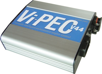
The Vi-PEC V44 is a V Series wire-in programmable engine-management ECU. Four injector and four ignition outputs, with an internal MAP sensor. Link's features table lists peak-and-hold drives while another hardware paragraph calls them optional; verify the exact V44 build and the manual before connecting low-impedance injectors. Link-hosted model information.
Wiring and pinout
The official V Series wiring and installation manual has the V44 header pinout, wiring diagrams and trigger sensor detail. Refer to the correct model and revision, as similar A-connector shells can have different functions, optional drivers and sensor circuitry.
Engine loom connector pinout
Transcribed from the Vi-PEC VX installation manual, pages 19. The connector view is looking into the ECU header or at the wire side of the loom; colours are for the documented loom and can differ in modified harnesses. Pin 22 can be used as analogue voltage 2 or digital input 4. Verify hardware, configuration and electrical limits against the source.
Connector A — 34-way
| Pin | Function | Loom colour in manual |
|---|---|---|
| 1 | Injector 4 | Brown/Orange |
| 2 | Injector 3 | Brown/Red |
| 3 | Injector 2 | Brown |
| 4 | Injector 1 | Brown/Black |
| 5 | +14 V | Red |
| 6 | +8 V | Red/White |
| 7 | Shield/Ground | Green |
| 8 | Trigger 1 | Black |
| 9 | Trigger 2 | Red |
| 10 | Ignition 4 | Blue/Orange |
| 11 | Ignition 3 | Blue/Red |
| 12 | Ignition 2 | Blue/Brown |
| 13 | Ignition 1 | Blue |
| 14 | Analogue voltage 4 | White/Black |
| 15 | Temperature 1 | Yellow |
| 16 | Temperature 2 | Yellow/Brown |
| 17 | Analogue voltage 1 | Yellow/Blue |
| 18 | Auxiliary 4 | Orange |
| 19 | Auxiliary 3 | Orange/Red |
| 20 | Auxiliary 2 | Orange/Brown |
| 21 | Auxiliary 1 | Orange/Black |
| 22 | Analogue voltage 2 or digital input 4 | White/Brown |
| 23 | Digital input 3 | Grey/Red |
| 24 | Sensor ground | Green |
| 25 | Ground | Black |
| 26 | Auxiliary 8 | Orange/Purple |
| 27 | Auxiliary 7 | Orange/Blue |
| 28 | Auxiliary 6 | Orange/Green |
| 29 | Auxiliary 5 | Orange/Yellow |
| 30 | Digital input 1 | Grey/Black |
| 31 | Digital input 2 | Grey/Brown |
| 32 | +5 V | Red/Blue |
| 33 | Analogue voltage 3 | Yellow/Black |
| 34 | Ground | Black |
Communications connector
The separate six-way connector is shown on page 22 of the same manual.
| Pin | Colour | Function |
|---|---|---|
| 1 | Brown | Ground |
| 2 | Blue | N/A |
| 3 | White | CAN high |
| 4 | Green | CAN low |
| 5 | Yellow | ECU RS232 transmit |
| 6 | Grey | ECU RS232 receive |
Tuning and software
Link lists VTS software and compatibility details for V Series ECUs. Choose the software matching the ECU firmware and keep a copy of the calibration before making changes. Link Vi-PEC software archive.