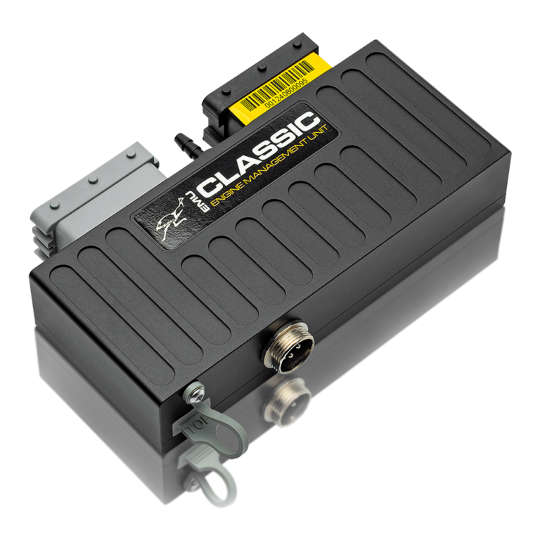
The universal EMU Classic is the successor to the original EMU. The manufacturer describes revised ignition outputs, a separate 5 V regulator, improved H-bridge protection and isolated USB; both share an EMU firmware and software family. Six high-impedance injector outputs and six ignition drivers are listed, with a built-in 4 bar MAP sensor, LSU 4.2 wideband controller and two EGT inputs. CAN and electronic throttle need external modules according to the manufacturer's comparison. Manufacturer product specification · Manufacturer comparison.
Connector pinout and wiring
Two FCI 24-way connectors. The black connector includes primary trigger at 7, ECU ground 17 and +5 V at 23. The grey connector has ignition coil 6 at 1, injector 1 at 7, +12 V power at 18 and power ground at 24. These positions are from the linked Classic diagram, not the Black ECU pinout. Exact-model manufacturer pinout.
The following assignments are from the ECUMaster EMU Classic pinout. Use its connector drawing to establish viewing orientation and cavity numbers. This is the universal EMU Classic; do not substitute EMU Black or vehicle-specific plug-in pin numbering.
Black 24-way connector
| Pin | Function |
|---|---|
| 1 | EGT input 1 |
| 2 | Knock sensor input 1 |
| 3 | Analogue input 2 |
| 4 | Coolant temperature input |
| 5 | Wideband Vs |
| 6 | Cam sync 2 |
| 7 | Primary trigger |
| 8 | Ignition coil 5 |
| 9 | EGT input 2 |
| 10 | Knock sensor input 2 |
| 11 | Analogue input 3 |
| 12 | Throttle position |
| 13 | Wideband Ip |
| 14 | Vehicle speed input |
| 15 | Cam sync 1 |
| 16 | Ignition coil 4 |
| 17 | ECU ground |
| 18 | Sensor ground |
| 19 | Analogue input 4 |
| 20 | Analogue input 1 |
| 21 | Air temperature |
| 22 | Wideband Vs/Ip |
| 23 | 5 V supply |
| 24 | Power ground |
Grey 24-way connector
| Pin | Function |
|---|---|
| 1 | Ignition coil 6 |
| 2 | Stepper motor 1 A |
| 3 | Stepper motor 2 A |
| 4 | AUX 6 |
| 5 | AUX 3 |
| 6 | Injector 4 |
| 7 | Injector 1 |
| 8 | Ignition coil 1 |
| 9 | Ignition coil 3 |
| 10 | Stepper motor 1 B |
| 11 | Stepper motor 2 B |
| 12 | AUX 5 |
| 13 | AUX 2 |
| 14 | Injector 5 |
| 15 | Injector 2 |
| 16 | Ignition coil 2 |
| 17 | Power ground |
| 18 | 12 V power |
| 19 | Wideband heater |
| 20 | AUX 4 / tacho |
| 21 | AUX 1 |
| 22 | Injector 6 |
| 23 | Injector 3 |
| 24 | Power ground |
Software and installation
Record the ECU serial, firmware, software and project versions and confirm assigned outputs and trigger inputs before connecting loads. The manufacturer downloads contain current software, manuals and supported base maps. Base maps do not establish the correct pinout for a particular vehicle. Compare with the ECUMaster family guide.