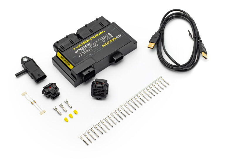
ECUMaster separately identifies an EMU Black plug-in for the Volkswagen R32 VR6 BFH engine, distinct from the BUB listing. Verify the actual engine code, car, connectors and gearbox configuration with the manufacturer before ordering or wiring. Model source · ECUMaster plug-in catalogue.
Wiring and pinout
The official download is named BFH pinout spreadsheet v2 and contains factory-connector and additional-connector tables. Its extracted text also labels terminal 66 “BUB radiator fan control”, so that applicability detail needs manufacturer confirmation. The table below reproduces every assignment in the BFH-labelled file; do not assume complete interchangeability with BUB. Manufacturer model-specific document.
Factory connector — source-listed assignments
The manufacturer's spreadsheet lists the following populated or assigned terminal numbers. Positions not listed in that source are not identified here as unused. PPS means pedal position sensor; DBW means drive-by-wire.
| Terminal | Vehicle function | EMU input / output in source |
|---|---|---|
| 1 | Power ground | Power ground |
| 2 | Power ground | Power ground |
| 3 | Main relay +12 V | |
| 4 | Second lambda heater | Internal WBO-to-CAN module |
| 5 | First lambda heater | WBO heater |
| 12 | Second lambda VGND | Internal WBO-to-CAN module VGND |
| 13 | Second lambda VS | Internal WBO-to-CAN module VS |
| 14 | Second lambda RCAL | Internal WBO-to-CAN module RCAL |
| 15 | Second lambda IP | Internal WBO-to-CAN module IP |
| 21 | Ignition +12 V | Ignition switch +12 V |
| 22 | Vacuum pump relay | H-bridge 2 B |
| 23 | Main relay | AUX 6 |
| 26 | Intake air temperature | IAT |
| 27 | IAT sensor ground | Sensor ground |
| 33 | PPS sensor ground | Sensor ground |
| 34 | PPS inverted | Analogue input 1 |
| 35 | PPS positive | TPS input |
| 36 | PPS sensor ground | Sensor ground |
| 37 | A/C engine speed signal | H-bridge |
| 39 | Clutch switch | Analogue input 5 |
| 41 | A/C signal | Analogue input 6 |
| 44 | Crankcase breather | AUX 4 |
| 51 | First lambda VGND | WBO VGND |
| 52 | First lambda IP | WBO IP |
| 55 | Brake switch | Analogue input 4 |
| 58 | CAN low | CAN low |
| 60 | CAN high | CAN high |
| 65 | AUX relay control | AUX 6 |
| 66 | BUB radiator fan control | AUX 5 |
| 70 | First lambda VS | WBO VS |
| 71 | First lambda RCAL | WBO Rcal |
| 72 | PPS +5 V | 5 V reference |
| 73 | PPS +5 V | 5 V reference |
| 82 | Crankshaft sensor | Primary trigger |
| 83 | DBW sensor ground | Sensor ground |
| 84 | DBW position sensor | Analogue 2 |
| 86 | Camshaft sensor | Secondary trigger |
| 87 | Camshaft sensor | Cam 2 |
| 88 | Injector 3 | Injector 3 |
| 89 | Injector 6 | Injector 6 |
| 90 | DBW sensor ground | Sensor ground |
| 91 | DBW +5 V | 5 V reference |
| 92 | DBW position sensor inverted | Analogue 3 |
| 93 | Coolant temperature sensor | CLT |
| 94 | Ignition coil 3 | Ignition coil 3 |
| 95 | Ignition coil 6 | Ignition coil 6 |
| 96 | Injector 1 | Injector 1 |
| 97 | Injector 5 | Injector 5 |
| 98 | CAM sensors +5 V | 5 V reference |
| 99 | Knock sensor ground | Sensor ground |
| 102 | Ignition coil 1 | Ignition coil 1 |
| 103 | Ignition coil 5 | Ignition coil 5 |
| 106 | Knock sensor 1 | Knock sensor 1 |
| 107 | Knock sensor 2 | Knock sensor 2 |
| 108 | Crank, coolant and knock sensor ground | Sensor ground |
| 110 | Ignition coil 2 | Ignition coil 2 |
| 111 | Ignition coil 4 | Ignition coil 4 |
| 112 | Injector 2 | Injector 2 |
| 113 | Injector 4 | Injector 4 |
| 115 | Intake variable valve solenoid | AUX 2 |
| 117 | DBW motor − | H-bridge 1 B |
| 118 | DBW motor + | H-bridge 1 A |
| 120 | Exhaust variable valve solenoid | AUX 1 |
| 121 | Intake variable-volume solenoid | AUX 3 |
Additional connector
| Terminal | Manufacturer function |
|---|---|
| 1 | Main relay +12 V |
| 2 | Power ground |
| 3 | CAN H |
| 4 | CAN L |
| 5 | RS232 TXD |
| 6 | RS232 RXD |
| 7 | Flex fuel input |
| 8 | +5 V reference |
| 9 | MAP sensor input |
| 10 | Analogue ground |
| 11 | EGT 2 input |
| 12 | Analogue ground |
| 13 | EGT 1 input |
| 14 | Analogue ground |
| 15 | MUX switch 3 input |
| 16 | Analogue ground |
| 17 | MUX switch 2 input |
| 18 | Analogue ground |
| 19 | MUX switch 1 input |
| 20 | +5 V reference |
| 21 | +5 V reference |
| 22 | +5 V reference |
| 23 | Analogue ground |
| 24 | Analogue ground |
| 25 | Analogue ground |
| 26 | Analogue ground |
Calibration and fitment checks
Record the engine code, ECU label and hardware, factory wiring and software version. The manufacturer provides software, available application notes and base maps; a base map is a starting point requiring checks of sensor readings, throttle operation, injector and ignition settings, trigger timing and engine calibration. Do not transfer universal EMU Black pin numbers or another plug-in's auxiliary connector assignments to this unit.
See the EMU Black model page and manufacturer index.