High or racing idle speeds and rich running on SU HS2, HS4, HS6, HD and HIF carburettors are two distinct problems that frequently occur together—an overly rich mixture can make idle hunt or surge, while air leaks or sticking linkages can mask mixture adjustments. When minor balancing and nut turns do not cure the issue, work through the mechanical checks below before changing needles.

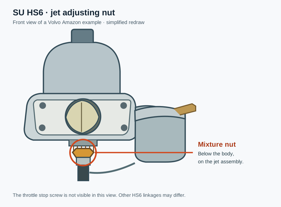

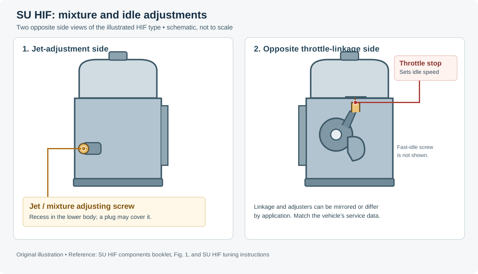
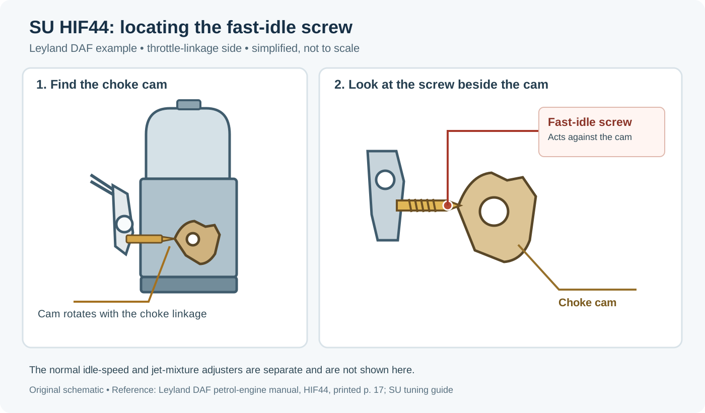
SU adjustment diagrams by type
Use the diagram for the carburettor fitted: linkage orientation and the controls differ between types and applications. These illustrations are hosted by SU Carburetters.
- H type: explanatory diagrams; see also the H-type tuning guide for throttle, jet nut and fast-idle adjustment.
- HD type: single-carb adjustment diagrams, including the slow-running valve, fast-idle screw and jet adjusting screw. On some multi-carb installations a throttle adjusting screw is used instead of the slow-running valve; see the HD multi-carb guide.
- HS type: throttle and jet adjustment diagrams. The first illustration identifies the idle-speed throttle screw (1) and mixture jet adjusting nut or screw (2); the later illustration identifies the fast-idle screw (4).
- HIF type: throttle and jet adjustment diagrams. The first illustration identifies the idle-speed throttle screw (1) and mixture jet adjusting screw (2); the later illustration identifies the fast-idle screw (4).

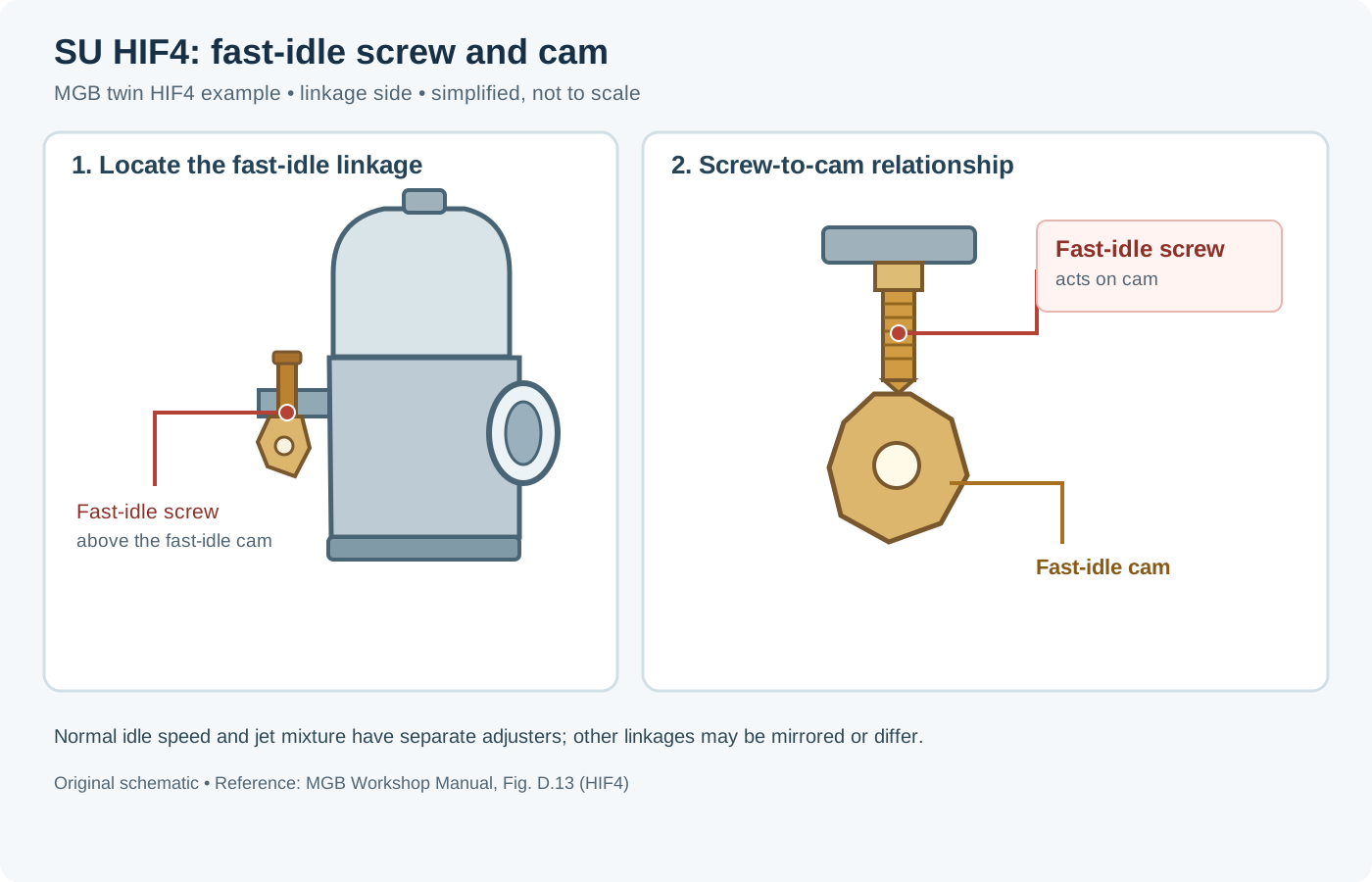
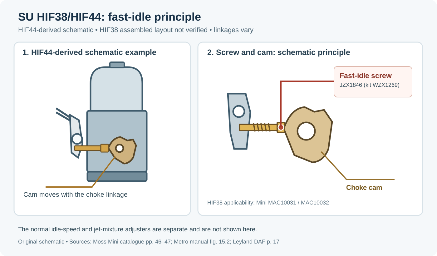
1. Diagnosing high, racing or erratic idle
Most road engines using SU carburettors target roughly 800–850 rpm at hot idle (rather than 500 rpm, which invites stalling, or 1,400–1,500 rpm caused by an air leak). Check these areas in order:
- Manifold & flange vacuum leaks: inspect the inlet gasket, spacer/insulator block and carburettor mounting flange for distortion, loose nuts or blown gaskets admitting unmetered air.
- Worn throttle spindles: with the throttle closed, check for radial play ("wiggle") at the throttle spindle ends. Worn bushes draw false air past the shaft, making it impossible to bring idle speed down with the tick-over screw and requiring spindle/bush refurbishment.
- Throttle-disc seating & orientation: the chamfered edge of a plain SU butterfly disc must face downwards onto the bore wall. Hold the body up to a light from behind—if diagonal slivers of light appear around the closed disc, slacken the disc screws, rotate/centre the disc until it snaps shut cleanly, and retighten.
- Overrun ("poppet") throttle valves: emissions-era throttle discs fitted with spring-loaded overrun poppet valves can hang open and cause erratic or high idle if the poppet spring weakens; replace faulty discs or fit plain discs where appropriate for the specification.
- Fast-idle screw & binding linkages: verify the fast-idle screw is not backed out so far that it holds the throttle open against the fast-idle cam—always set normal idle speed first, then set fast idle. Check that cross-shafts, cables and return springs move freely without binding.
- Off-centre jet (fixed-needle carbs): on non-biased fixed-needle HS, H and HD units, if the jet is off-centre the needle binds against the jet bore and stops the piston dropping fully onto the bridge, holding airflow and idle high.
2. Diagnosing rich running and flooding
Symptoms include an uneven exhaust note, sooty spark plugs, black exhaust tailpipes, fuel dripping from the throat or overflow, bore washing and crankcase oil dilution.
- Float-lid needle valve & debris: rust or dirt from the tank or fuel lines lodges in the float-chamber needle valve, or a worn Viton/brass needle tip fails to seal, letting fuel rise over the jet into the bridge. Inspect tank/lines, fit a clean inline filter and replace suspect needle valves.
- Punctured float or wrong float height: older hollow plastic or brass floats can leak and sink. On HS float lids, invert the lid with the needle shut and check the gap between the underside of the float and the lid face—SU/Burlen specifies roughly
1/16 into3/16 in(3–4.5 mm), consistent across twin/triple sets. On HD lids, insert an11.0 mm(7/16 in) bar between the forked lever and the lid lip. - Excess fuel pump pressure: too much pump pressure vibrates ("fibrillates") the needle off its seat, letting excess fuel creep past at idle and low load. Check regulated delivery pressure against the carburettor specification.
- Sticking choke / jet return: on H, HD and HS units, pulling the choke first advances fast idle and then drops the jet. A sticky cable, binding cam lever or gummed jet bearing can leave the jet stuck partly lowered after the knob is pushed home.
- Air filters, damper oil & camshaft reversion: clogged air filters enrich the mixture by choking airflow. Always top up piston dampers with SAE 20 oil (no thicker than SAE 30). Modified or high-overlap "hot" camshafts increase intake reversion and normally need a rolling-road needle selection rather than a standard profile.
- Mismatched jet and needle bore: never run a
0.090 inneedle inside a0.100 injet—the oversized annular gap will flood the engine across the range.
3. Mixture adjustment, jet centring and balancing
Lifting-pin mixture check
With the engine fully warm and idling, press the spring-loaded lifting pin underneath the body (lifting the piston roughly 1/32 in off the bridge) and release it:
- Momentary slight RPM rise then settles: mixture is correct.
- RPM rises and stays high: mixture is too rich.
- RPM drops immediately or engine stalls: mixture is too lean.
Jet adjustment by SU family
| SU Family | Baseline starting setting | Direction to richen / lean |
|---|---|---|
| HS (HS2 / HS4 / HS6 / HS8) | Raise jet nut until top of jet is flush with the bridge, then unscrew (clockwise viewed from above) 9 flats (fixed needle) or 14 flats (spring-loaded bias needle). | Viewed from above in situ: turn nut anti-clockwise (screw in / up) to lean; turn clockwise (unscrew / down) to richen. |
| HIF (HIF4 / HIF6 / HIF7 / HIF38 / HIF44) | Set jet flush with bridge or follow vehicle manual baseline (jet does not drop for choke; rotary valve handles cold start). | Screw mixture screw in to lower the jet via the bi-metal lever (richen); unscrew out to raise the jet (lean). Immersed bi-metal blade automatically compensates for fuel temperature/viscosity. |
| HD (HD4 / HD6 / HD8) | Set butterfly fully closed; idle speed is set via the side bypass metering screw, and mixture via the external fork screw. | Requires removing float chamber and diaphragm housing to slacken the locking nut when centring the jet against the fully raised jet and lightly pressed piston rod. |
Piston drop check and airflow balancing
With the jet fully up and damper removed, lift and release the piston—it must fall smoothly and land on the bridge with a crisp metallic click. On twin and triple SU installations, disconnect or slacken the cross-couplings at idle and use a Synchrometer or Uni-Syn airflow meter in each intake throat to match idle airflow across all carburettors before tightening the couplings and setting final mixture.
Related pages
- SU carburettors: types, sizing and models
- SU needle profile database
- Carburettor tuning, jetting and setup
- Carburettor synchronisation, faults and rebuilds
Sources
- SU Carburetters / Burlen Ltd: How To Fix Idle and Rich Mixture Issues in HS Type Carburetters (HS2, HS4 & HS6). Spindle wear, throttle-disc orientation, float height (`3–4.5 mm`), lift-pin test, and 9/14-flat initial settings.
- SU Carburetters / Burlen Ltd: HD Type Routine Servicing. Jet centring, `11.0 mm` (`7/16 in`) float check bar, and needle shoulder/groove alignment.
- SU Carburetters / Burlen Ltd: Type HIF Carburetter Design, Adjustment & Fuel Compensation.