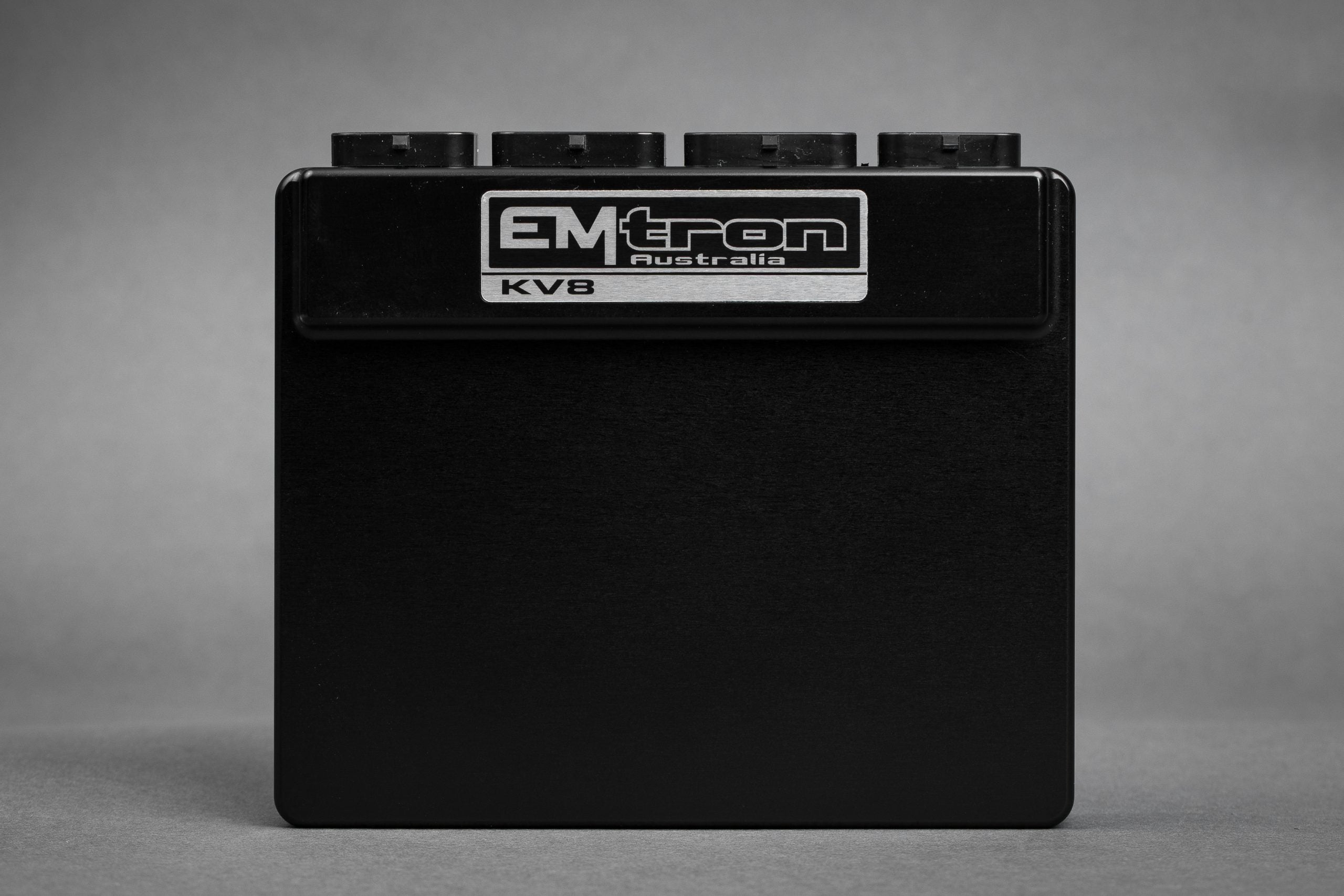
Emtron KV8 is a programmable standalone ECU from Emtron Australia. Eight port-injector and eight ignition channels, dual LSU 4.9 lambda channels, 16 auxiliary outputs and up to two electronic throttles are listed for the KV8. Emtron KV8 datasheet.
Identification and configuration
Record the ECU model, serial, board revision and loaded firmware. The Emtune calibration determines the use of configurable inputs and outputs; electrical limits, ignition driver type, injector impedance and wired supplies must be checked for the actual unit. Emtron engine-management manual.
Connector pinouts — revision 2
These tables reproduce the positions in Emtron's KV8 Rev2 pinout. The source diagrams are viewed looking into the ECU connector. NC is the manufacturer's unconnected designation. Verify connector keying, revision, power, grounds and all limits in the original before wiring; assignments differ between models and hardware revisions.
Connector A
| Pin | Channel Name |
|---|---|
| A1 | NC |
| A2 | NC |
| A3 | NC |
| A4 | NC |
| A5 | NC |
| A6 | NC |
| A7 | NC |
| A8 | NC |
| A9 | NC |
| A10 | Lambda 1 Heater - |
| A11 | Lambda 2 Heater - |
| A12 | NC |
| A13 | NC |
| A14 | NC |
| A15 | NC |
| A16 | Lambda 1 Heater + |
| A17 | Lambda 2 Heater + |
| A18 | Lambda 1 Nernst Cell (Vs) |
| A19 | NC |
| A20 | Lambda 2 Cal Resistor (CalR) |
| A21 | Lambda 2 Nernst Cell (Vs) |
| A22 | Lambda 2 Pump Cell (Ip) |
| A23 | Lambda 2 Virtual Ground (VGnd) |
| A24 | Lambda 1 Cal Resistor (CalR) |
| A25 | Lambda 1 Pump Cell (Ip) |
| A26 | Lambda 1 Virtual Ground (VGnd) |
Connector B
| Pin | Channel Name | Pin | Channel Name |
|---|---|---|---|
| B1 | Injection Channel 1 | B18 | Auxiliary Output 9 |
| B2 | Injection Channel 2 | B19 | Auxiliary Output 10 |
| B3 | Injection Channel 3 | B20 | Auxiliary Output 11 |
| B4 | Injection Channel 4 | B21 | Auxiliary Output 12 |
| B5 | Injection Channel 5 | B22 | Auxiliary Output 13 |
| B6 | Injection Channel 6 | B23 | Auxiliary Output 14 |
| B7 | Injection Channel 7 | B24 | Auxiliary Output 15 |
| B8 | Injection Channel 8 | B25 | Auxiliary Output 16 |
| B9 | ECU Ground | B26 | Ignition Channel 1 |
| B10 | Auxiliary Output 1 | B27 | Ignition Channel 2 |
| B11 | Auxiliary Output 2 | B28 | Ignition Channel 3 |
| B12 | Auxiliary Output 3 | B29 | Ignition Channel 4 |
| B13 | Auxiliary Output 4 | B30 | Ignition Channel 5 |
| B14 | Auxiliary Output 5 | B31 | Ignition Channel 6 |
| B15 | Auxiliary Output 6 | B32 | Ignition Channel 7 |
| B16 | Auxiliary Output 7 | B33 | Ignition Channel 8 |
| B17 | Auxiliary Output 8 | B34 | ECU Ground |
Connector C
| Pin | Channel Name | Pin | Channel Name |
|---|---|---|---|
| C1 | ECU Ground | C18 | Digital Input 9 |
| C2 | Analog Input Channel 1 | C19 | Digital Input 10 |
| C3 | Analog Input Channel 2 | C20 | Digital Input 11 |
| C4 | Analog Input Channel 3 | C21 | Digital Input 12 |
| C5 | Analog Input Channel 4 | C22 | Digital Input 13 |
| C6 | Analog Input Channel 5 | C23 | Digital Input 14 |
| C7 | Analog Input Channel 6 | C24 | Analog Input Channel 16 |
| C8 | Analog Input Channel 7 | C25 | Analog Sensor 0V Reference |
| C9 | Analog Input Channel 8 | C26 | ECU Ground |
| C10 | Analog Input Channel 9 | C27 | Digital Input 1 |
| C11 | Analog Input Channel 10 | C28 | Digital Input 2 |
| C12 | Analog Input Channel 11 | C29 | Digital Input 3 |
| C13 | Analog Input Channel 12 | C30 | Digital Input 4 |
| C14 | Analog Input Channel 13 | C31 | Digital Input 5 |
| C15 | Analog Input Channel 14 | C32 | Digital Input 6 |
| C16 | Analog Input Channel 15 | C33 | Digital Input 7 |
| C17 | Analog Sensor 0V Reference | C34 | Digital Input 8 |
Connector D
| Pin | Channel Name |
|---|---|
| D1 | ECU 14V Supply |
| D2 | Auxiliary Output 13-16 14V Supply |
| D3 | Sensor Supply 8V |
| D4 | Crank Index Sensor + |
| D5 | Crank Index Sensor - |
| D6 | Sync Sensor + |
| D7 | Sync Sensor - |
| D8 | CAN 1H |
| D9 | EFI Relay Output (Low Side 200mA) |
| D10 | CAN 2H |
| D11 | Knock 1 + |
| D12 | Knock 1 - |
| D13 | Shield (Crank/Cam/ Knock) |
| D14 | CAN 1L |
| D15 | Ignition Switch Input |
| D16 | CAN 2L |
| D17 | Knock 2 + |
| D18 | Knock 2 - |
| D19 | Analog Output (0.0 - 5.0V) |
| D20 | Auxiliary Output 9-12 14V Supply |
| D21 | Sensor Supply Vref1: 5.0V |
| D22 | Sensor Supply Vref2: 5.0V |
| D23 | Ethernet Tx + |
| D24 | Ethernet Tx - |
| D25 | Ethernet Rx + |
| D26 | Ethernet Rx - |
Sensor 0 V references and main ECU grounds have distinct wiring requirements. H-bridge supplies and relay control require the installation described in the manufacturer's power-distribution guide. See Emtron wiring index and revision-specific diagrams.