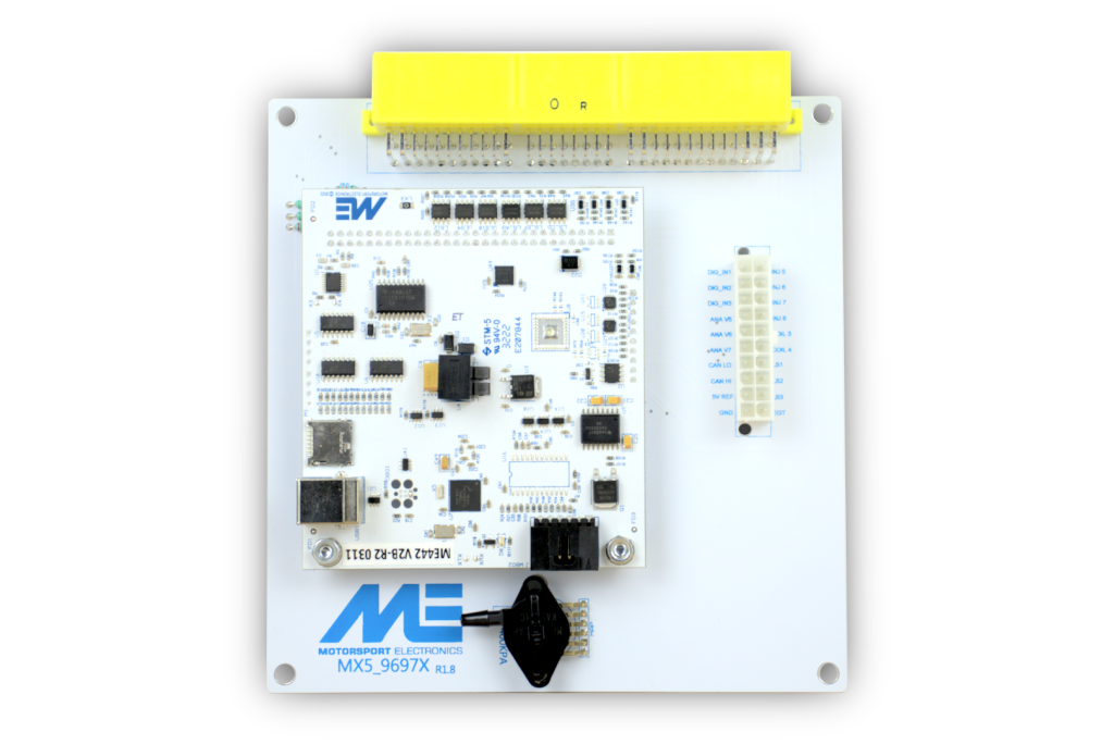
ME442 plug-in ECU for Mazda MX-5 Mk2 1999–2000. This application-specific unit replaces the factory ECU electronics while using the vehicle's original harness connector, subject to exact fitment and configuration. Motorsport Electronics product information · application installation guide.
Identification and application
The manufacturer identifies this as the NB three-plug application. Verify the original board and connector and use the matching base map and board-switch configuration. Record the serial, board version, firmware, factory ECU part number, engine and transmission before installing. The ME221 and ME442 are separate hardware choices; the manufacturer lists wideband, onboard logging and EGT as ME442 plug-in features. Optional electronic throttle equipment and supported functions vary by board and configuration. See ME's model comparison and downloads.
Connector and pinout
Use the OEM header and auxiliary connector diagrams in the exact application installation guide. Connector view, jumper/switch settings, sensors and supported functions vary by generation and vehicle. The universal 28-way and 90-way wire-in tables do not define this plug-in board's factory header.
OEM header assignments
Documented positions from the manufacturer application guide, looking into the ECU connector from the loom wire side. Positions not shown in that guide are not asserted here. Functions and auxiliary DBW availability depend on model, board revision, hardware and configuration.
| Pin | Function in manufacturer guide |
|---|---|
| 1B | Ignition 12 V |
| 1E | CEL / LS13 |
| 1i | AC blower relay / LS16 |
| 1K | DBW motor +, auxiliary, optional ME442 DBW only |
| 1N | DBW motor −, auxiliary, optional ME442 DBW only |
| 1O | Alternator control / LS4 (R1.4), COIL 8 (R1.5), COIL 5 (R1.8 onwards) |
| 1P | Air-con switch / DIGIN 5 |
| 1Q | Battery light / LS12 |
| 1R | Primary fan relay / LS15 |
| 1S | AC clutch relay / LS14 |
| 2B | Inlet-air temperature / ANA T1 |
| 2C | O2 sensor / ANA V3 |
| 2D | VSS speed / DIGIN 4 |
| 2E | Coolant sensor / ANA T2 |
| 2F | Knock sensor + / KNOCK 1 |
| 2H | Cam sensor / VR_CAMA |
| 2i | TPS 5 V reference |
| 2J | Crank sensor / VR_CRANK |
| 2K | Tachometer |
| 2L | MAF signal / ANA V4 |
| 3A/B/C | Grounds |
| 3E | Throttle signal / ANA V2 |
| 3G | Ignition 1 & 4 / COIL 1 |
| 3H | Ignition 2 & 3 / COIL 2 |
| 3i | Clutch switch / DIGIN 6, not all models |
| 3L | Purge solenoid / boost / LS10 |
| 3N/3P | Fuel pump relay / LS11 |
| 3O | PWM idle valve / LS9 |
| 3Q | VICS solenoid / LS17 |
| 3W | Injector 1 |
| 3X | Injector 2 |
| 3Y | Injector 3 |
| 3Z | Injector 4 |
| MAP | On-board MAP / ANA V1 |
The guide lists several board-revision alternatives for alternator control at 1O; its footnote describes R1.5-and-later IGN 8 while its table lists COIL 5 for R1.8 onwards. Confirm the actual board with ME.
Auxiliary connector assignments
The ME GEN2 installation guide lists this 20-way Molex Mini-Fit Jr connector. Check the original diagram for orientation, the actual model and fitted options: the table describes the documented connector, not a guarantee every function is supported on every ME221 or ME442 core.
| Pin | Function in manufacturer guide |
|---|---|
| 1 | Injector 5 — 3.5 A FB protected |
| 2 | Injector 6 — 3.5 A FB protected |
| 3 | Injector 7 — 3.5 A FB protected |
| 4 | Injector 8 — 3.5 A FB protected |
| 5 | Coil 3 — 50 mA TTL |
| 6 | Coil 4 — 50 mA TTL |
| 7 | LS1 — 2 A PWM-capable |
| 8 | LS2 — 2 A PWM-capable |
| 9 | LS3 — 2 A PWM-capable |
| 10 | K-type EGT signal — ME442 only |
| 11 | DI 1 — 1 kΩ 5 V pull-up |
| 12 | DI 2 — 1 kΩ 5 V pull-up |
| 13 | DI 3 — 1 kΩ 5 V pull-up |
| 14 | Analogue volt 5 — 0–5 V |
| 15 | Analogue volt 6 — 0–5 V |
| 16 | Analogue volt 7 — 0–5 V |
| 17 | CAN 1 low |
| 18 | CAN 1 high |
| 19 | 5 V reference — 100 mA max |
| 20 | EGT and sensor ground |
The guide calls pin 13 “DI 3” but describes it as “Digital Input 2” in parentheses; the inconsistency is retained here as DI 3 and requires confirmation.
Software and installation
Use the correct MEITE / EZ Tune release and the model-specific firmware and base map. The installation guide covers sensor settings, baseline checks, expansion, jumper settings and any vehicle-specific exceptions; a base map still needs calibration and verification on the actual engine. See the ME442 family page for wire-in generation and hardware context.
Sources reviewed 17 November 2026.