What is K-Jetronic?
Bosch K-Jetronic is a mechanically metered, continuous petrol injection system for the intake ports, often called CIS (continuous injection system). Bosch lists its 1973 introduction on the Porsche 911. The basic system meters fuel with an airflow sensor and a hydraulic fuel distributor; it does not pulse the main injectors electrically. Later K-Jetronic installations could add electronic lambda feedback. [1, 2]
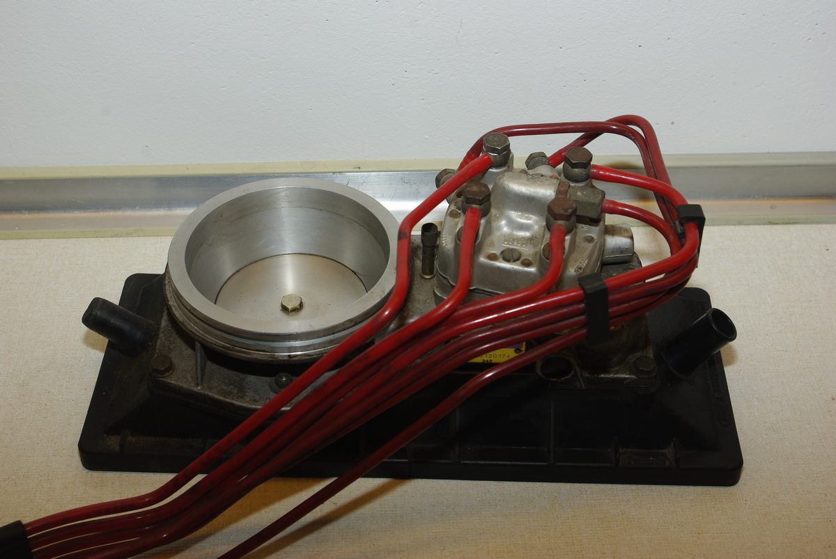

How fuel is metered
- An electric pump sends fuel through the filter and accumulator to the fuel distributor. The system-pressure regulator controls supply pressure and returns excess fuel. The accumulator helps retain pressure after shutdown, assisting hot restarting.
- Air entering the engine deflects a sensor plate in a shaped air funnel. A lever moves a control plunger in the fuel distributor, exposing more or less of a metering slit for each cylinder.
- Differential-pressure valves in the distributor regulate flow through the metering circuits. Separate fuel lines carry the metered fuel to the individual intake-port injection valves.
- When cold, the warm-up regulator lowers control pressure acting against the metering mechanism. For a given airflow the plate and plunger can move further, enriching the mixture; control pressure rises as the regulator warms. Some versions also use manifold pressure for load enrichment. [2]
What kind of injectors?
The main K-Jetronic injectors are spring-loaded mechanical valves. Fuel pressure opens each valve; its needle can vibrate rapidly to help atomise the spray. The distributor meters fuel quantity, and the valves spray continuously when sufficient pressure and fuel flow are present. Fuel can collect near a closed intake valve until the engine draws it in. Bosch also describes air-shrouded versions, which use additional air to improve atomisation. These are not solenoid injectors controlled by pulse width. [2]
Do not confuse the main injectors with the separate electrically operated cold-start valve fitted to many installations: it supplies additional fuel during cold cranking under its own temperature/time control. An auxiliary-air device can supply extra bypass air during warm-up. Exact equipment varies. [3]
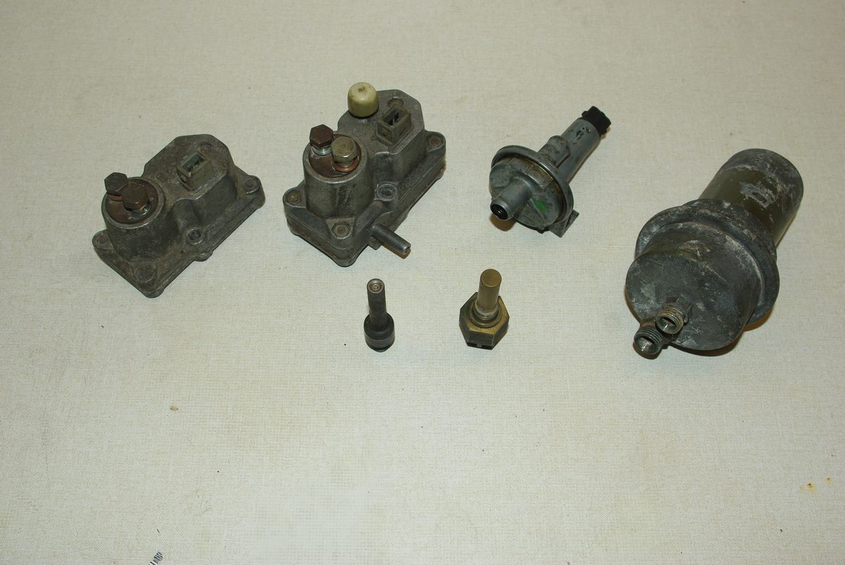

K-Jetronic with lambda control
Basic K-Jetronic is open loop. On K-Jetronic with lambda control, an oxygen sensor and electronic controller add a correction to the mechanical base metering. The controller varies the duty cycle of a pulsed electromagnetic frequency valve (also called a timing valve), altering fuel pressure in the distributor's differential-pressure circuits and therefore the amount delivered. The main injectors remain continuously spraying mechanical valves. Feedback normally depends on operating conditions and sensor temperature; the exact strategy is application-specific. [2, 4]
A lambda sensor or an electronic box alone does not make a system KE-Jetronic: K-lambda and KE use different hydraulic control arrangements. Earlier D-Jetronic uses electrically pulsed main injectors and an analogue ECU.
Identification and workshop checks
- Look for the airflow plate, fuel distributor and one rigid or reinforced fuel line per cylinder; confirm the system with the vehicle and Bosch component numbers.
- Cold and warm control pressure, system pressure and residual pressure are different measurements. Compare each with the specification and test arrangement for the exact vehicle and regulator; do not transfer figures between applications.
- Air leaks downstream of the airflow sensor, fuel supply problems, a sticking sensor plate or plunger, and injector spray or leakage can affect running. Check the basic mechanical and ignition condition before changing mixture settings.
- For lambda-equipped versions, establish whether the system is in feedback and check the sensor, electrical supply and frequency-valve operation using the vehicle procedure. Base mixture adjustments require the specified conditions and appropriate exhaust measurement.
Fuel systems can retain pressure after the engine is stopped. Follow the applicable workshop procedure before opening any fuel connection.
Sources
- [1] Bosch Classic: spare parts brochure, Jetronic history and component descriptions.
- [2] Bosch technical instruction: K-Jetronic, independent PDF mirror; airflow measurement, mechanical injectors, warm-up and lambda control.
- [3] Bosch Classic: K-Jetronic teaching diagram, including the optional lambda-control components.
- [4] Rolls-Royce workshop manual TSD 4737, fuel injection, independent reproduction; K-Jetronic and lambda-control example. Accessed 10 November 2026.