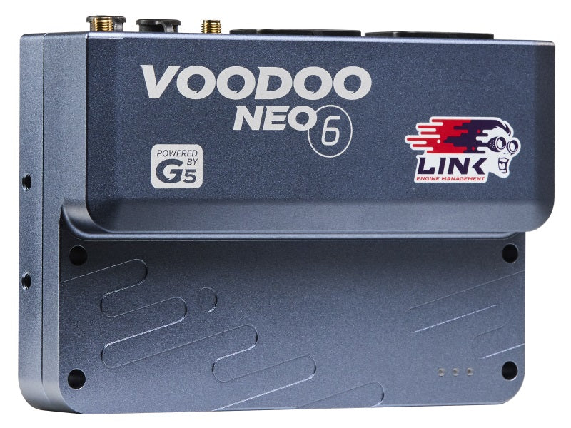
Link G5 Voodoo Neo 6 is a programmable G5 wire-in engine-management ECU. Manufacturer lists up to eight-cylinder control. Some injection and digital-input functions share hardware; count only channels available in the chosen configuration. Link G5 Voodoo Neo 6 quick-start guide.
Model identification and I/O
| Item | Documented details |
|---|---|
| ECU family | G5 |
| Outputs | 12 injection and 8 ignition drives |
| Programming | PCLink version matched to ECU generation and firmware |
| Connector and loom | See the exact-model guide, including connector keys, wire-side orientation and optional functions |
The manufacturer guidance and wiring identify the hardware; driver counts do not establish injector electrical compatibility or imply all multiplexed pins can be used at the same time.
Model-specific pinout and installation
The G5 Voodoo Neo 6 quick-start guide provides the connector diagrams and installer I/O table. Refer to that version for numbered cavities, wire colours, supply, grounds, driver and sensor connection notes. Loom wire-side and ECU header views are identified on the diagram; do not transfer a pin number from another generation.
Software and further sources
Download software, firmware and full installation help from Link's download centre; identify the ECU generation and installed firmware before choosing a PCLink package. The legacy software list separates G5, G4X and G4+ compatibility. See also Link standalone ECUs.
Neo 6 A and B header pinouts
Positions follow Link's G5 Neo 6 installer I/O table, version 2; the manufacturer’s quick-start shows the view looking into the ECU header, equivalent to the loom wire side. The Neo 4 and Neo 6 differ at A19, A27–A29 and B29–B30. ADIO and shared pins are configurable; see the original for current limits, pull-ups, grounding, fuses and each mode's restrictions.
Header A
| Pin | Function |
|---|---|
| A1 | Injection 4 |
| A2 | Injection 3 |
| A3 | Injection 2 |
| A4 | Injection 1 |
| A5 | +14 V ECU supply |
| A6 | Ignition switch input |
| A7 | Trigger shield ground |
| A8 | Trigger 1 |
| A9 | Trigger 2 |
| A10 | Ignition 4 |
| A11 | Ignition 3 |
| A12 | Ignition 2 |
| A13 | Ignition 1 |
| A14 | ADIO 1 |
| A15 | Analogue temperature 1 |
| A16 | Analogue temperature 2 |
| A17 | Analogue voltage 1 |
| A18 | Aux 3 / H-bridge 1 |
| A19 | Injection 9 / digital input 7 |
| A20 | Aux 2 |
| A21 | Aux 1 |
| A22 | Analogue voltage 2 |
| A23 | Digital input 3 |
| A24 | Sensor ground |
| A25 | Ground |
| A26 | Aux 4 / H-bridge 1 |
| A27 | Injection 12 / digital input 10 |
| A28 | Injection 11 / digital input 9 |
| A29 | Injection 10 / digital input 8 |
| A30 | Digital input 1 |
| A31 | Digital input 2 |
| A32 | +5 V output |
| A33 | Analogue voltage 3 |
| A34 | Ground |
Header B
| Pin | Function |
|---|---|
| B1 | Injection 8 |
| B2 | Injection 7 |
| B3 | Injection 6 |
| B4 | Injection 5 |
| B5 | +14 V E-throttle supply |
| B6 | Analogue temperature 3 |
| B7 | Analogue temperature 4 |
| B8 | Knock 2 |
| B9 | Knock 1 |
| B10 | Wideband heat |
| B11 | Wideband MES |
| B12 | Ignition 6 |
| B13 | Ignition 5 |
| B14 | Wideband RE |
| B15 | ADIO 3 |
| B16 | ADIO 4 |
| B17 | Knock shield ground |
| B18 | Aux 5 / H-bridge 2 |
| B19 | Digital input 6 |
| B20 | Digital input 5 / K-line |
| B21 | Digital input 4 |
| B22 | Sensor ground |
| B23 | ADIO 5 |
| B24 | ADIO 6 |
| B25 | Ground |
| B26 | Aux 6 / H-bridge 2 |
| B27 | CAN 2 high |
| B28 | CAN 2 low |
| B29 | Ignition 8 |
| B30 | Ignition 7 |
| B31 | Wideband IPE |
| B32 | Wideband APE |
| B33 | ADIO 2 |
| B34 | Ground |
Link identifies A5 as main supply, A6 as switched ignition input and B5 as H-bridge supply. Follow the matching guide for grounding and power distribution; USB power does not provide all normal hardware functions.