MaxxECU RACE H2O — Water-protected version of the original MaxxECU RACE; the manufacturer lists an IP67 enclosure. MaxxECU product information.
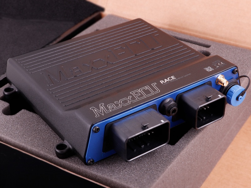
Model identification and capabilities
The product listing specifies eight peak-and-hold injector outputs and eight ignition outputs, up to eight sequential cylinders, dual knock inputs, one wideband input and eight EGT inputs via a separate harness. It lists four motor outputs, two 12 V outputs and nine low-driving auxiliary outputs. Manufacturer specification; MaxxECU model comparison.
| Sequential cylinders, maximum | 8 |
|---|---|
| Injector outputs | 8 peak-and-hold |
| Ignition outputs | 8 |
| Configuration | MTune; check the release appropriate to the ECU and hardware revision |
Identification and installation
RACE H2O is distinct from the newer GEN2 RACE. Check the enclosure, part number, harness and hardware revision against the manufacturer’s wiring information; do not transfer GEN2 connector numbers to it.
Record the model label, serial number, hardware revision, firmware, connector keying and loom. Outputs can be assigned or share functions; supported functions also depend on available I/O and software configuration. The figure in the comparison is a controller capability, not proof of compatibility with a particular engine or vehicle.
Connector and pinout
The manufacturer’s wiring reference distinguishes GEN1 RACE from GEN2. Confirm the RACE H2O unit and its harness against the matching drawing before using any table. These positions are manufacturer-labelled ECU functions, not an assurance that a particular loom or calibration uses them. Exact wiring and connector reference.
The MaxxECU distributor's H2O kit list includes the RACE/V1/PRO connector 1 loom, RACE connector 2 loom and RACE wiring diagram. The following RACE connector assignments are therefore relevant to that documented kit; verify the specific H2O unit, loom and revision.
RACE connector 1
| Position | Manufacturer function | Notes |
|---|---|---|
| A1 | GPO 5 | |
| A2 | IGN 1 | |
| A3 | IGN 2 | |
| A4 | GPO 8/TACHO | 660ohm pullup |
| B1 | GPO 6 | |
| B2 | IGN 3 | |
| B3 | IGN 4 | |
| B4 | GPO 1 | |
| C1 | GPO 7 | |
| C2 | IGN 5 | |
| C3 | IGN 6 | |
| C4 | GPO 2 | |
| D1 | WBO2 Heater- | |
| D2 | IGN 7 | |
| D3 | IGN 8 | |
| D4 | GPO 3 | |
| E1 | CAN H | |
| E2 | CAN L | |
| E3 | GND Shield | |
| E4 | GPO 4 | |
| F1 | CLT | |
| F2 | IAT | |
| F3 | WBO2 VREF | |
| F4 | WBO2 VS | |
| G1 | +5V sensor supply | (peak 0.5A, max 150mA) |
| G2 | TPS/AIN | |
| G3 | WBO2 IP | |
| G4 | WBO2 RCAL | |
| H1 | Sensor GND | |
| H2 | Trigger GND | |
| H3 | TRIGGER | |
| H4 | HOME | |
| J1 | AIN 1 (Temperature) | |
| J2 | AIN 2 (Temperature) | |
| J3 | AIN 3 (0-5V) | |
| J4 | AIN 4 (0-5V) | |
| K1 | INJ 1 | |
| K2 | INJ 2 | |
| K3 | DIN/VR 1 | |
| K4 | DIN/VR 2 | |
| L1 | INJ 8 | |
| L2 | INJ 7 | |
| L3 | INJ 6 | |
| L4 | Engine GND | |
| M1 | INJ 3 | |
| M2 | INJ 4 | |
| M3 | INJ 5 | |
| M4 | +12V ECU power supply |
RACE connector 2
From the manufacturer’s GEN1 connector reference; check connector view, hardware revision and current ratings in the original.
| Position | Manufacturer function | Notes |
|---|---|---|
| A1 | egt 5+ | |
| A2 | egt 6+ | |
| A3 | egt 7+ | |
| A4 | egt 8+ | |
| B1 | egt 5- | |
| B2 | egt 6- | |
| B3 | egt 7- | |
| B4 | egt 8- | |
| C1 | EGT 1 + | |
| C2 | EGT 2+ | |
| C3 | EGT 3+ | |
| C4 | EGT 4+ | |
| D1 | EGT 1- | |
| D2 | EGT 2- | |
| D3 | EGT 3- | |
| D4 | EGT 4- | |
| E1 | KNOCK GND | |
| E2 | Knock 1 | |
| E3 | knock 2 | |
| E4 | AIN 6 (0-5v) | |
| F1 | ain 7 (0-5v) | |
| F2 | ain 8(0-5V) | |
| F3 | din/vr 4 | |
| F4 | din/vr5 | |
| G1 | gpo 15(+12v) | |
| G2 | gpo 16 (+12v) | |
| G3 | ain 5 (0-5V) | |
| G4 | eNGINE GROUND | |
| H1 | mOTOR 2+ | |
| H2 | mOTOR 1- | |
| H3 | mOTOR 2- | |
| H4 | mOTOR 1+ |
Consult the full diagram for wiring, grounds, supply fuses, driver limits, connector orientation and remaining positions. Sensor grounds and power grounds have different purposes; follow the matching manual.
Software and further documents
- MaxxECU RACE H2O: product information
- Model wiring and pinout reference
- MTune, quick-start guides and revision-specific wiring downloads
- MaxxECU family overview
Sources reviewed 17 November 2026.