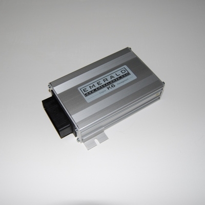
Emerald K3 is an Emerald engine-management designation. Produced February 2007 to April 2010, K3 is documented with six injector drivers and three internal ignition coil drivers. Its features include adaptive lambda using a compatible external wideband controller, triple map switching and CAN dashboard data. Emerald manufacturer information.
Identification and configuration
Identify the exact hardware and serial number. Emerald notes that some units have bespoke software for non-standard installations, and that many M3DK units were upgraded to K3 specification. An old case label alone cannot establish the internal specification. Emerald earlier ECU information; software and manuals.
Emerald provides a K3/K6 software family separately from M3DK software. Its K6 generic and preconfigured packages are ordering/configuration choices; a base map is a starting point requiring matching and calibration for the actual engine.
Pinout, harness and software
The K3-specific connector pin table is transcribed in the manufacturer overview; check the manufacturer's K3 manual v057 and the ECU's configuration. Manufacturer manual or documentation. Use terminal markings, exact connector view and the source's wiring and driver notes. A model-specific adapter for an original vehicle harness is distinct from the generic connector assignment.
See Emerald adapter catalogue and Emerald standalone ECU overview.
Example pinout: Emerald K3 main connector
36-way positions and generic functions from Emerald K3 manual v057, page 56. Use moulded cavity numbers and the manufacturer's connector drawing to establish viewing orientation; do not assume this is a K6, K6+ or bespoke ECU pinout.
| Pin | Function |
|---|---|
| 1 | Injector 4 / AuxOut1 |
| 2 | IACV2 / AuxOut2 |
| 3 | IACV1 / IACV PWM / AuxOut3 |
| 4 | Ignition 3 / main relay |
| 5 | Ignition 2 / AuxOut5 |
| 6 | Cooling fan relay |
| 7 | Narrowband oxygen signal, 0–1 V |
| 8 | Throttle position signal |
| 9 | +5 V sensor supply, 100 mA maximum |
| 10 | AuxIn10 |
| 11 | Ignition sense, switched +12 V |
| 12 | Tacho |
| 13 | Immobiliser / EGT digital input |
| 14 | +8 V sensor supply |
| 15 | Cam phase / custom input |
| 16 | Air temperature |
| 17 | Injector 5 / ignition 4 / AuxOut17 |
| 18 | Oxygen sensor signal earth |
| 19 | Shift light / AuxOut19 |
| 20 | Fuel pump relay |
| 21 | Injector 6 / configurable auxiliary output |
| 22 | IACV3 / AuxOut22 |
| 23 | Injector 2 |
| 24 | Injector 1 |
| 25 | Ignition 1 |
| 26 | Injector 3 / AuxOut26 |
| 27 | IACV4 / AuxOut27 |
| 28 | +12 V ignition supply |
| 29 | ECU earth |
| 30 | Sensor earth |
| 31 | Main trigger input |
| 32 | Main trigger sensor earth |
| 33 | Coolant temperature |
| 34 | AuxIn34 |
| 35 | AuxIn35 |
| 36 | AuxIn36 / AuxOut36 |
Slash-separated functions depend on configuration. The K3 manual describes driver outputs except tacho as switched earths, and specifies high-impedance injectors or appropriately sized ballast for low-impedance injectors. Confirm hardware and configuration before connecting coils and injectors.
COMMS nine-way connector
Race Technology’s K3/K6 CAN integration instructions identify the left-hand COMMS connector and the following RS232 and CAN assignments. Check orientation and firmware on the actual ECU; its CAN protocol may require configuration.
| Pin | Function |
|---|---|
| 1 | CAN high |
| 2 | CAN low |
| 3 | Not used |
| 4 | Not used |
| 5 | Signal earth |
| 6 | Not used |
| 7 | RS232 receive |
| 8 | RS232 transmit |
| 9 | RS232 clear to send |