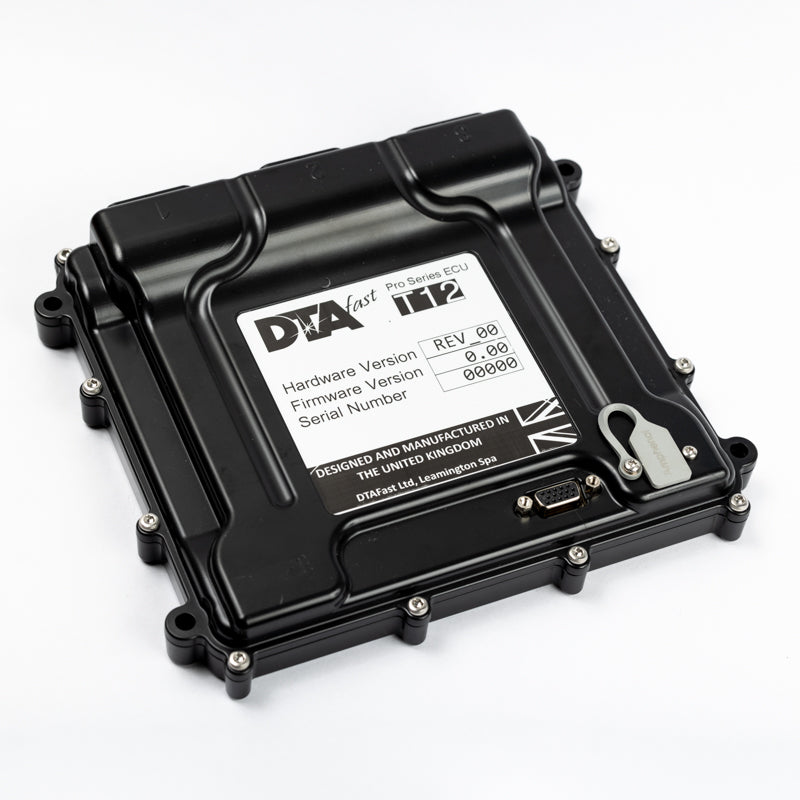
Up to twelve cylinders with fully sequential injection and ignition. DTAFast T12 product information.
Features and application
Four variable cam controls and paddle-shift support are listed by DTAFast. Use the manufacturer's model-specific diagrams to allocate connector cavities and configure inputs. All T-series units use the T-Series PC software; DTAFast describes configurable inputs and outputs, integrated Bosch wideband measurement, logging, firmware updates and a built-in trigger oscilloscope. Available functions and channel limits depend on the exact model and firmware. Manufacturer specification.
Identification and wiring
Identify the printed model including any “+” or “i” suffix, hardware revision, connector and firmware before allocating pins. Configurable functions may differ from defaults. Manufacturer T12 wiring diagram and connector pinout contains connector orientation, cavity functions, power, earth and sensor examples. Follow its fuse and load requirements; do not interchange pin numbering with another T-series controller.
Source discrepancy: DTAFast’s file linked as the T12 wiring diagram is titled “T12+ ECU” in its connector pages as retrieved on 17 November 2026. The T12 and T12+ are listed separately by the manufacturer; confirm the correct non-plus T12 pinout directly with DTAFast before wiring.
Software and related information
DTAFast provides model-specific wiring diagrams, firmware, manuals and PC software via its downloads section. Capture the existing calibration and firmware identifiers before making changes. See the DTAFast family overview for earlier S and E series models.