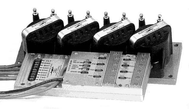
The TEC R-88 is a historic TEC-I family engine-management configuration for high-performance eight-cylinder engines with large injectors or two injectors per cylinder. The manufacturer describes a separate direct-fire unit, with the controller and ignition coil packs able to be mounted separately. Electromotive TEC installation manual, page 5.
Wiring and terminal identification
The manufacturer’s model-specific wiring diagram is on page 44 of the TEC installation manual. It depicts spade and hard-wired connections rather than one universal numbered multipin connector. It shows a sensor/communications block marked CLT, GND, MAT, GND, KNK, EGO, GND, TXD and RXD; adjacent outputs are marked fuel-pump relay, tach, check engine and spare. The illustrated injector modules use FI1–FI4 terminals. Record the exact unit and configuration, and follow the complete wiring, power, relay and direct-fire diagrams rather than assuming compatibility with TEC-II.
Identification
TEC-I was offered in several configurations, including R-88, 6-cylinder dual-plug, 12-cylinder and three-rotor applications. Injector and ignition wiring depends on configuration. Electromotive manual, pages 5 and 41–44.
Return to Electromotive standalone ECUs.
R-88 illustrated terminal schedules
The printed labels below are taken from the Electromotive's TEC installation manual. They identify the terminals shown in the drawings; they are not manufacturer-numbered connector cavities. Other plugs and wiring vary with the actual ECU, injector drivers and engine. Consult the complete drawing and check the markings on the unit. The TEC-I fuel-pump relay terminal is a ground-switching output; it differs from the TEC-II output described in the manual.
The specific R-88 drawing on page 44 depicts the sensor/communications terminals in the order shown below, top to bottom. The positions are identified by printed label, not manufacturer pin number.
Sensor and communications terminals
| Marking or lead | Documented function |
|---|---|
| CLT | Coolant temperature sensor |
| GND | Ground adjacent to CLT |
| MAT | Manifold air temperature sensor |
| GND | Ground adjacent to MAT |
| KNK | Knock sensor input |
| EGO | Exhaust-gas oxygen sensor signal |
| GND | Ground |
| TXD | Transmit data |
| RXD | Receive data |
Adjacent output terminals
| Marking or lead | Documented function |
|---|---|
| F.P. RELAY | Fuel-pump relay control; TEC-I uses a pull-to-ground output |
| TACH | Tachometer output |
| CHECK ENG. | Check-engine light output |
| SPARE | Optional general-purpose output; build-dependent |
R-88 FI injector-driver markings
| Marking or lead | Documented function |
|---|---|
| FI1 | Injector-driver terminal for coil A event; repeated on second driver bank |
| FI2 | Injector-driver terminal for coil B event; repeated on second driver bank |
| FI3 | Injector-driver terminal for coil C event; repeated on second driver bank |
| FI4 | Injector-driver terminal for coil D event; repeated on second driver bank |
Illustrated power leads
| Marking or lead | Documented function |
|---|---|
| ECU red (+) lead | Positive supply, shown through main-power relay |
| ECU black (−) lead | Ground |
| Direct-fire unit red (+) lead | Positive supply, shown through main-power relay |
| Direct-fire unit black (−) lead | Ground |
The drawing shows two four-driver banks with FI1–FI4 repeated. The manual describes these as injector ground drivers and discusses use of the second bank for the R-88. Verify driver capacity, coil firing sequence and the separately switched injector supply against the exact build and manual.