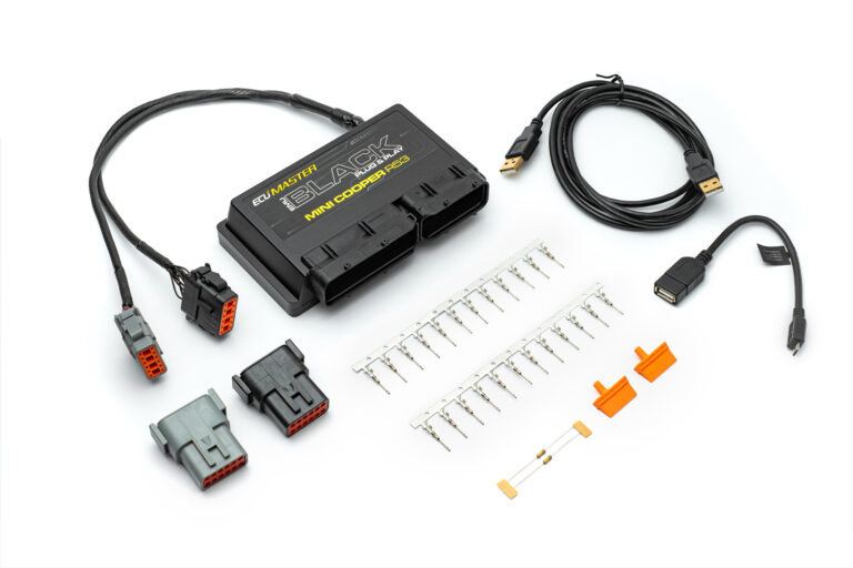
The EMU Black MINI R53 plug-in uses the MINI factory ECU connectors in an application-specific ECU enclosure. The v1.0 application note describes drive-by-wire, a factory CAN stream, configurable knock control and wideband LSU 4.2/4.9 support. It describes a stock R53 starting calibration, not a calibration suitable without checks for every modified engine. Model source · ECUMaster plug-in catalogue.
Wiring and pinout
Application note v1.0, page 14, gives the black and grey auxiliary harness connector assignments shown below. Positions are in source order; refer to its diagrams for connector view, sensor connections, driver limits and installation conditions. Manufacturer model-specific document.
Black auxiliary connector
| Terminal | Manufacturer function |
|---|---|
| 1 | H-bridge 2 B |
| 2 | H-bridge 2 A |
| 3 | Wideband oxygen heater |
| 4 | Wideband oxygen Ip |
| 5 | Wideband oxygen Vs |
| 6 | Wideband oxygen Rcal |
| 7 | Wideband oxygen VGnd |
| 8 | AUX 6 |
| 9 | Injector 5 |
| 10 | Injector 6 |
| 11 | Battery +12 V |
| 12 | Power ground |
Grey auxiliary connector
| Terminal | Manufacturer function |
|---|---|
| 1 | CAN high |
| 2 | CAN low |
| 3 | RS232 TX |
| 4 | RS232 RX |
| 5 | Flex fuel input |
| 6 | EGT 2 |
| 7 | EGT 1 |
| 8 | MUX switch 2 |
| 9 | MUX switch 1 |
| 10 | Ignition +12 V |
| 11 | 5 V reference |
| 12 | Analogue ground |
The source's spare-input summary refers to MUX switches 2 and 3, but its connector table labels grey terminals 8 and 9 as MUX switches 2 and 1. The table above reproduces the connector table; confirm the intended signal with ECUMaster before use. The source does not give a numbered full factory-connector pinout, so do not infer one from these auxiliary connectors.
Wideband sensor connections
The application note specifies the following connection mapping for the black auxiliary harness; unplug the original narrowband sensor as directed by the manual. These sensor terminal numbers refer to each Bosch sensor connector, not the ECU connector.
| Black harness terminal | Function | LSU 4.2 terminal | LSU 4.9 terminal |
|---|---|---|---|
| 3 | Heater | 4 | 3 |
| 4 | Ip | 6 | 1 |
| 5 | Vs | 1 | 6 |
| 6 | Rcal | 2 | 5 |
| 7 | VGnd | 5 | 2 |
| 11 | +12 V | 3 | 4 |
Calibration and fitment checks
Record the engine code, ECU label and hardware, factory wiring and software version. The manufacturer provides software, available application notes and base maps; a base map is a starting point requiring checks of sensor readings, throttle operation, injector and ignition settings, trigger timing and engine calibration. Do not transfer universal EMU Black pin numbers or another plug-in's auxiliary connector assignments to this unit.
See the EMU Black model page and manufacturer index.