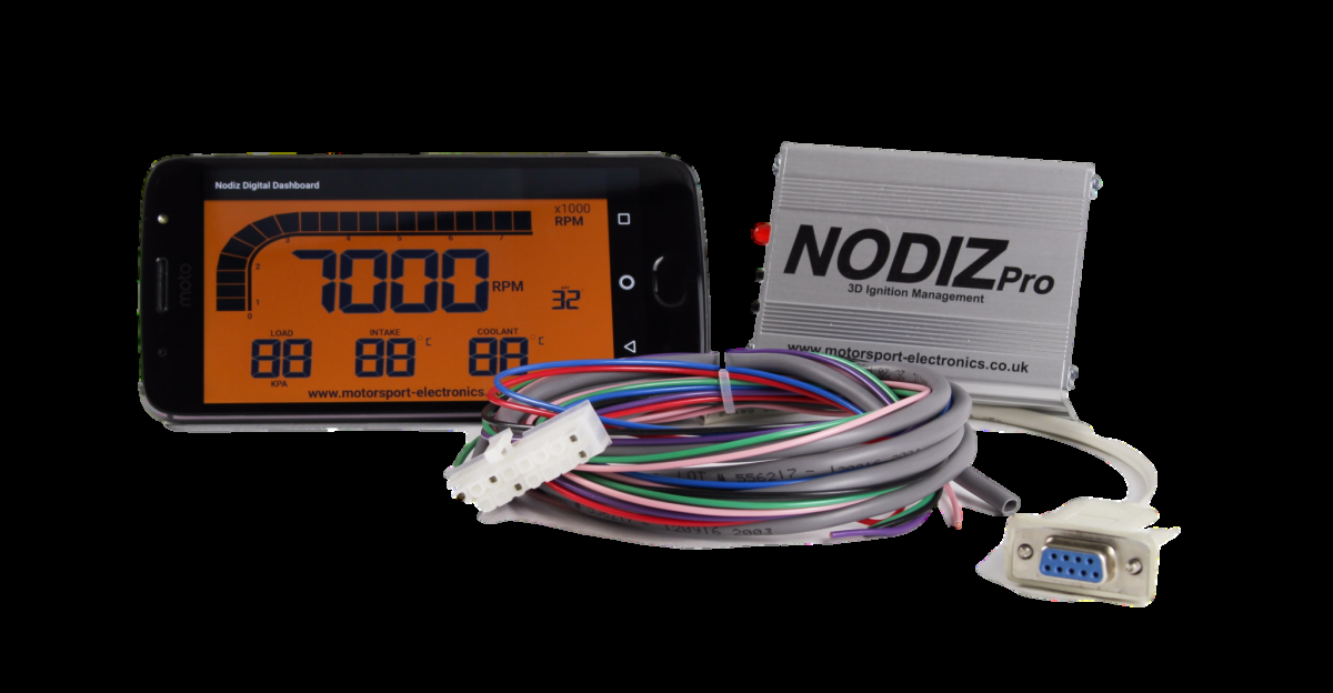
ME lists NODIZ Pro GEN2 as an earlier ignition-only controller with its own installation guide, separately from NODIZ GEN-X. It is not a fuel-injection ECU. Record the unit's label and revision before choosing documentation. Manufacturer documentation · ME manuals and downloads.
Identification and configuration
Record the complete model label, serial number, hardware generation, firmware and harness. Wire-in ECUs and vehicle-specific plug-in versions have different physical connections. Software and output assignments depend on the unit and calibration; follow the appropriate manufacturer wiring guide and check the installed configuration.
Wiring reference
Use the NODIZ Pro GEN2 installation guide under ME's support downloads. A verified inline pinout has not been transcribed here; do not assume GEN-X wiring applies to GEN2.
Software and further information
ME provides MEITE / EZ Tune, firmware and installation guides on its support page. Confirm the software and firmware required by the actual unit. See Motorsport Electronics ECU family.
Sources reviewed 17 November 2026.
Manufacturer 20-way connector table
From section 6.2 of the NODIZ Pro Gen2 installation and tuning manual. The connector is described as a 20-way Molex 39-01-2205; colours shown are those specified for the factory loom, and a dash means the table does not specify a colour. Coil output use and firing order differ by cylinder count; consult the model manual.
| Pin | Factory loom colour | Function |
|---|---|---|
| 1 | Blue | Coil B negative feed, switched earth |
| 2 | — | Tachometer output for 12 V tachometers |
| 3 | — | Launch control active when connected to earth |
| 4 | — | Coil C negative feed, switched earth |
| 5 | — | Not connected |
| 6 | Pink | TPS / MAP sensor signal |
| 7 | — | Coil D negative feed, switched earth |
| 8 | — | Crank sensor white, inside shielded cable |
| 9 | — | Crank sensor black, inside shielded cable |
| 10 | Green | Coil A negative feed, switched earth |
| 11 | Yellow | RS232 receive |
| 12 | Black | Ground and RS232 ground |
| 13 | Black | Ground |
| 14 | — | Shift light output, 500 mA switched earth |
| 15 | — | Inlet air temperature sensor |
| 16 | Purple | TPS / MAP sensor reference, 5 V |
| 17 | — | Coolant temperature sensor |
| 18 | — | Programmable output, 500 mA switched earth |
| 19 | Orange | RS232 transmit |
| 20 | Red | 12 V main power, ignition switched |