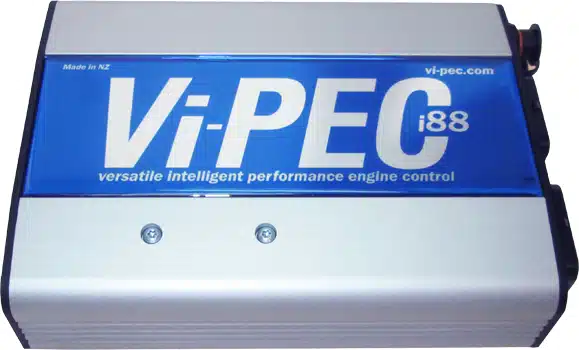
The Vi-PEC i88 is a iSeries wire-in programmable engine-management ECU. 8 injector and 8 ignition outputs; the iSeries manual describes an A and B connector, peak-and-hold injector drives and an external MAP sensor. Link’s archived page describes electronic throttle, two-sensor knock control and variable camshaft control. Link-hosted model information.
Wiring and pinout
The official iSeries wiring and installation manual has the i88 header pinout, wiring diagrams and trigger sensor detail. Refer to the correct model and revision, as similar A-connector shells can have different functions, optional drivers and sensor circuitry.
Engine loom connector pinout
The Vi-PEC iSeries installation manual, pages 20–21, shows the connector viewed into the ECU header or from the wire side of the loom. Numbers below follow the manual's connector diagram; colours describe its standard loom and may differ in a modified harness. The i88 uses separate A and B connectors; B14 is marked not connected. Confirm configuration, pull-ups and electrical limits in the original before wiring.
Connector A — 34-way
| Pin | Function | Loom colour in manual |
|---|---|---|
| 1 | Injector 4 | Brown/Orange |
| 2 | Injector 3 | Brown/Red |
| 3 | Injector 2 | Brown |
| 4 | Injector 1 | Brown/Black |
| 5 | +14 V | Red |
| 6 | +8 V | Red/White |
| 7 | Shield/Ground | Green |
| 8 | Trigger 1 | Black |
| 9 | Trigger 2 | Red |
| 10 | Ignition 4 | Blue/Orange |
| 11 | Ignition 3 | Blue/Red |
| 12 | Ignition 2 | Blue/Brown |
| 13 | Ignition 1 | Blue |
| 14 | Analogue voltage 4 | White/Black |
| 15 | Temperature 1 | Yellow |
| 16 | Temperature 2 | Yellow/Brown |
| 17 | Analogue voltage 1 | Yellow/Blue |
| 18 | Auxiliary 4 | Orange |
| 19 | Auxiliary 3 | Orange/Red |
| 20 | Auxiliary 2 | Orange/Brown |
| 21 | Auxiliary 1 | Orange/Black |
| 22 | Analogue voltage 2 | White/Brown |
| 23 | Digital input 3 | Grey/Red |
| 24 | Ground out | Green |
| 25 | Ground | Black |
| 26 | Auxiliary 8 | Orange/Purple |
| 27 | Auxiliary 7 | Orange/Blue |
| 28 | Auxiliary 6 | Orange/Green |
| 29 | Auxiliary 5 | Orange/Yellow |
| 30 | Digital input 1 | Grey/Black |
| 31 | Digital input 2 | Grey/Brown |
| 32 | +5 V | Red/Blue |
| 33 | Analogue voltage 3 | Yellow/Black |
| 34 | Ground | Black |
Connector B — 34-way
| Pin | Function | Loom colour in manual |
|---|---|---|
| 1 | Injector 8 | Brown/Purple |
| 2 | Injector 7 | Brown/Blue |
| 3 | Injector 6 | Brown/Green |
| 4 | Injector 5 | Brown/Yellow |
| 5 | +14 V Aux 9/10 | Red |
| 6 | Temperature 3 | Yellow/Red |
| 7 | Temperature 4 | Yellow/Orange |
| 8 | Knock 2 | Blue |
| 9 | Knock 1 | Blue |
| 10 | Ignition 8 | Blue/Purple |
| 11 | Ignition 7 | Blue/Black |
| 12 | Ignition 6 | Blue/Green |
| 13 | Ignition 5 | Blue/Yellow |
| 14 | Not connected | — |
| 15 | Analogue voltage 6 | White/Red |
| 16 | Analogue voltage 7 | White/Orange |
| 17 | Shield/Ground | Green |
| 18 | Auxiliary 9 | Purple |
| 19 | Digital input 6 | Grey/Green |
| 20 | Digital input 5 | Grey/Yellow |
| 21 | Digital input 4 | Grey/Orange |
| 22 | Ground out | Green |
| 23 | Analogue voltage 8 | White/Yellow |
| 24 | Analogue voltage 9 | White/Green |
| 25 | Ground | Black |
| 26 | Auxiliary 10 | Purple/White |
| 27 | Digital input 10 | Grey/Purple |
| 28 | Digital input 9 | Grey/White |
| 29 | Digital input 8 | Grey |
| 30 | Digital input 7 | Grey/Blue |
| 31 | Analogue voltage 10 | White/Blue |
| 32 | Analogue voltage 11 | White |
| 33 | Analogue voltage 5 | Yellow/Green |
| 34 | Ground | Black |
Communications connector
The six-way communications connector is separate from the engine loom connectors. iSeries installation manual; confirm orientation in the diagram.
| Pin | Wire | Function |
|---|---|---|
| 1 | Brown | Ground |
| 2 | Blue | Not connected |
| 3 | White | CAN high |
| 4 | Green | CAN low |
| 5 | Yellow | ECU RS232 transmit |
| 6 | Grey | ECU RS232 receive |
Tuning and software
Link identifies PCLink for G4+ as compatible with iSeries ECUs. Choose the software matching the ECU firmware and keep a copy of the calibration before making changes. Link Vi-PEC software archive.