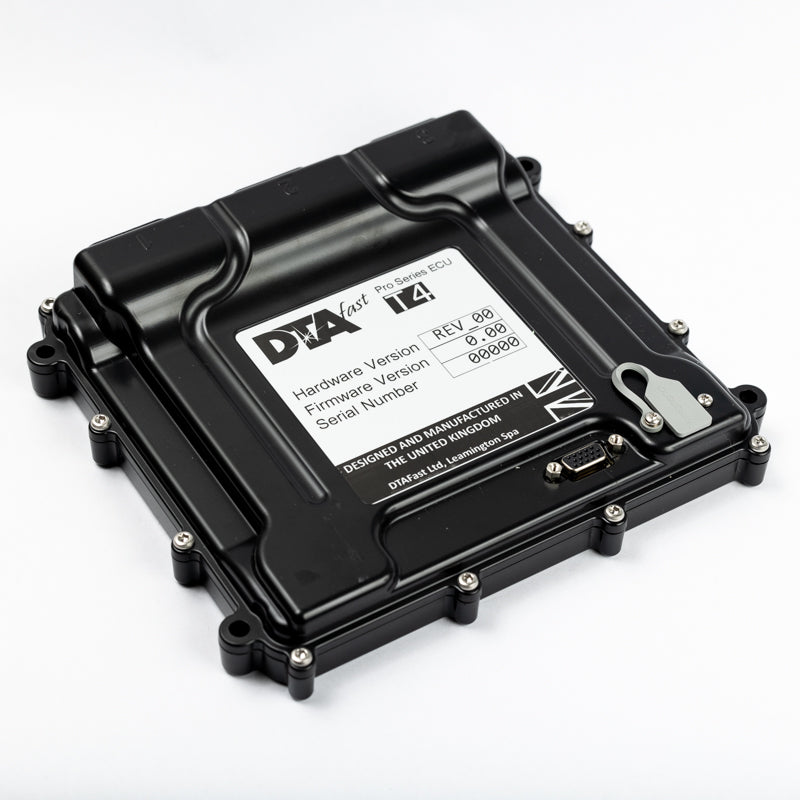
Four-cylinder fully sequential injection and ignition; the manufacturer also describes six- and eight-cylinder semi-sequential operation. DTAFast T4 product information.
Features and application
Features listed include traction control and a single variable camshaft control. Its moulded enclosure differs from the larger metal-cased range. All T-series units use the T-Series PC software; DTAFast describes configurable inputs and outputs, integrated Bosch wideband measurement, logging, firmware updates and a built-in trigger oscilloscope. Available functions and channel limits depend on the exact model and firmware. Manufacturer specification.
Identification and wiring
Identify the printed model including any “+” or “i” suffix, hardware revision, connector and firmware before allocating pins. Configurable functions may differ from defaults. Manufacturer T4 wiring diagram and connector pinout contains connector orientation, cavity functions, power, earth and sensor examples. Follow its fuse and load requirements; do not interchange pin numbering with another T-series controller.
T4 connector pinouts — version 1.04
Manufacturer diagram specifies pin-insertion side. The tables below include labelled positions; unlisted positions are shown as a dash in the source and should not be assigned. T4 is not T4+. DTAFast T4 wiring diagram v1.04
Connector 1
| Pin | Function |
|---|---|
| 1 | Coil 3 |
| 3 | PWM 3 |
| 4 | PWM 2 |
| 5 | PWM 1 |
| 9 | Injector 1 |
| 10 | Coil 1 |
| 13 | Power ground 1 |
| 14 | Power ground 2 |
| 17 | Injector 2 |
| 18 | Coil 2 |
| 25 | Injector 4 |
| 26 | Coil 4 |
| 31 | Ignition 12 V in |
| 34 | Injector 3 |
Connector 2
| Pin | Function |
|---|---|
| 1 | Analogue 2 |
| 2 | Wheel 1 |
| 3 | Analogue 10 |
| 4 | Digital 1 |
| 5 | Analogue 3 |
| 6 | Analogue 4 |
| 7 | Thermistor 1 |
| 9 | 5 V output |
| 10 | Analogue 1 |
| 12 | Crank sensor |
| 14 | Digital 4 |
| 15 | Digital 5 |
| 16 | Analogue 11 |
| 17 | Thermistor 3 |
| 19 | Analogue 6 |
| 21 | Sensor ground |
| 22 | Cam 1 |
| 24 | 5 V output |
| 25 | Thermistor 2 |
| 26 | CAN high |
| 28 | CAN low |
| 33 | Sensor ground |
| 34 | Analogue 9 |
Connector 3
| Pin | Function |
|---|---|
| 7 | Lambda 1 pump current |
| 8 | Lambda 1 VGND |
| 9 | Lambda 1 heater negative |
| 10 | PWM 8 |
| 11 | Lambda 1 trim resistor |
| 12 | Lambda 1 Nernst voltage |
| 17 | Analogue 7 |
| 18 | Analogue 8 |
| 22–25 | PWM 4–7 respectively |
| 26–27 | Permanent 12 V |
In this diagram the permanent 12 V supply must be fused. Hardware revision affects pull-ups; see the original wiring instructions.
Confirm the exact ECU, hardware revision and connector orientation before wiring. Configurable functions and electrical limits are model-dependent; consult the linked original diagrams.
Software and related information
DTAFast provides model-specific wiring diagrams, firmware, manuals and PC software via its downloads section. Capture the existing calibration and firmware identifiers before making changes. See the DTAFast family overview for earlier S and E series models.