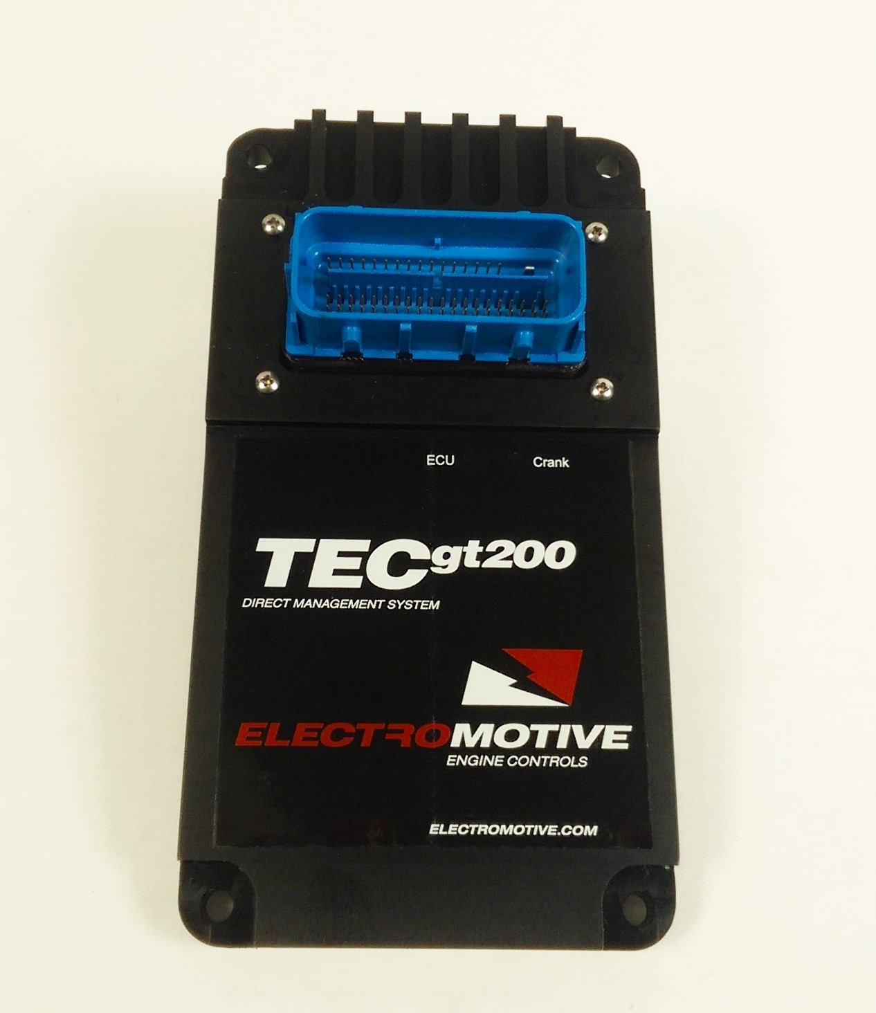
Electromotive TECgt200 is a model in the Total Engine Control family. The TECgt200 is the higher-I/O 200-series engine controller, listed by the manufacturer for supported engines up to 12 cylinders. Manufacturer source.
Identification and software
Identify the exact model, serial, firmware and ignition-driver configuration before using a calibration or connecting a loom. WinTEC versions and hardware vary; the Electromotive manual archive separates the generations.
Wiring and pinout
Consult the model-specific manufacturer source and technical archive for the matching connector, firing order, ECU earths, injector drivers and ignition connections. Do not transfer TECgt200 or TECs200 positions to earlier TEC units. Where a complete exact-model pinout has not been verified, use the manufacturer documentation and verify the actual part number.
Availability
As of 17 November 2026, the manufacturer states it is not selling or repairing products. Electromotive notice. See the Electromotive family reference.
Hardware specification
The manufacturer lists six saturated injector drivers, sequential injection up to six cylinders, six high-current inductive and six logic-level coil drivers, nine general-purpose inputs and nine outputs, CAN, USB and serial communication. Supported 8- and 12-cylinder applications are not equivalent to individual sequential injector channels for each cylinder. TECgt200 product specification.
Manufacturer connector schedule
The following TECgt200 ECU connector schedule is from Electromotive's model-specific installation manual. Functions marked as alternatives depend on configuration; consult the manual for electrical ratings, connector view and harness details. The pin list identifies the manual's default functions; optional and assigned functions depend on the unit and configuration.
| Pin | Function |
|---|---|
| 1 | Coil shield |
| 2 | Coil A1 |
| 3 | Coil B1 |
| 4 | Coil C1 |
| 5 | DoC A1 |
| 6 | DoC B1 |
| 7 | DoC C1 |
| 8 | Ground |
| 9 | Knock |
| 10 | DoC A2 |
| 11 | DoC B2 |
| 12 | DoC C2 |
| 13 | Coil shield |
| 14 | Coil A2 |
| 15 | Coil B2 |
| 16 | Coil C2 |
| 17 | Ground |
| 18 | Ground |
| 19 | 5 V reference |
| 20 | 5 V reference |
| 21 | 5 V reference |
| 22 | GPI 2 |
| 23 | GPI 3 |
| 24 | GPI 4 |
| 25 | GPI 5 |
| 26 | GPI 6 |
| 27 | GPI 7 |
| 28 | GPI 8 |
| 29 | GPI 9 |
| 30 | Ground |
| 31 | RXD |
| 32 | TXD |
| 33 | 12 V input |
| 34 | Speed input |
| 35 | USB ground |
| 36 | USB PC 5 V |
| 37 | USB D− |
| 38 | USB D+ |
| 39 | Cam input |
| 40 | Cam 2 |
| 41 | Ground |
| 42 | Crank sensor input |
| 43 | Ground |
| 44 | MAP |
| 45 | TPS |
| 46 | CLT |
| 47 | MAT |
| 48 | EG RTD |
| 49 | EGO primary |
| 50 | EGO secondary |
| 51 | CAN high |
| 52 | CAN low |
| 53 | 12 V input |
| 54 | GPO 7 |
| 55 | GPO 2 |
| 56 | Data log status |
| 57 | Fuel pump relay |
| 58 | GPO 1 |
| 59 | Check engine |
| 60 | IAC B / GPO 4 |
| 61 | IAC A / GPO 3 |
| 62 | Tach |
| 63 | GPO 9 / VVT |
| 64 | GPO 8 / VVT |
| 65 | IAC D / GPO 6 |
| 66 | IAC C / GPO 5 |
| 67 | Injector 1 |
| 68 | Injector 2 |
| 69 | Injector 3 |
| 70 | Injector 4 |
| 71 | Injector 5 |
| 72 | Injector 6 |
| 73 | Main ground |