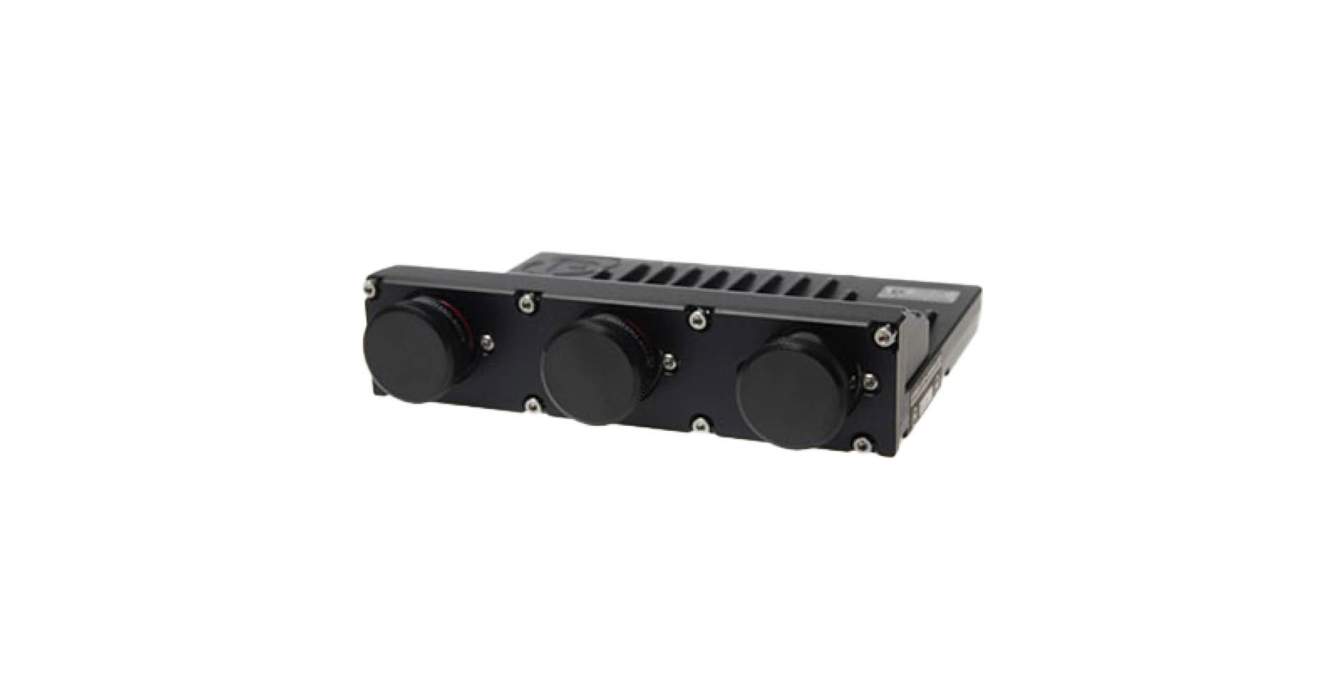
The SQ6M motorsport ECU has 12 configurable injector drivers, eight IGBT and eight logic-level ignition outputs; Cosworth describes its Deutsch Autosport connectors and 4 MB internal logging. Cosworth product information.
Identification and control
Cosworth lists software features including fly-by-wire, dual lambda, launch and traction, with paddle-shift control as an option. Obtain the matching SQ6M connector information from Cosworth; SQ6 88-way pinout does not apply by default. Document the exact part number, serial, software build, calibration, championship configuration and any security or software option before assessing compatibility.
Connectors and wiring
Review the model-specific Cosworth document and request the current build sheet where necessary. Connector and driver assignments may be model-, build- and configuration-dependent. Sensor supplies, peak driver currents, earths and high-voltage injector circuits must be matched to the official document.
Software and support
Cosworth's Pectel application notes cover model-specific strategies; confirm toolchain and access level with the supplier. See the Cosworth Pectel and Antares family for related controllers.
Complete documented connector schedules
The tables transcribe all 107 positions from the manufacturer’s Pectel SQ6M product information 29E-071520-5E, pages 3–6, hosted by RB Racing. Connector identification is corroborated by AiM’s SQ6M guide. Pin letters are case-sensitive. I = input, O = output, I/O = bidirectional. See the manufacturer source for connector view, pin ratings, fusing, driver and ground requirements; confirm the exact hardware and software revision before wiring. Pin functions may be configurable.
Connector 1 — AS216-26PN, mating AS616-26SN
| Pin | Direction | Signal |
|---|---|---|
| L | Battery | VBAT |
| M | Battery | VBAT |
| Y | Battery | ECU GND |
| Z | Battery | ECU GND |
| a | Battery | ECU GND |
| K | O | IGN1 |
| J | O | IGN2 |
| H | O | IGN3 |
| G | O | IGN4 |
| F | O | IGN5 |
| E | O | IGN6 |
| X | O | INJ1 |
| W | O | INJ2 |
| A | O | INJ3 |
| R | O | INJ4 |
| B | O | INJ5 |
| T | O | INJ6 |
| C | O | INJ7 |
| U | O | INJ8 |
| D | O | INJ9 |
| V | O | INJ10 |
| b | O | PWM1 |
| c | O | PWM2 |
| P | O | PWM3 |
| S | O | PWM4 |
| N | O | PWM5 |
Connector 2 — AS216-35PN, mating AS616-35SN
| Pin | Direction | Signal |
|---|---|---|
| 1 | I/O | ANG GND |
| 2 | I | AIN4 |
| 3 | I | AIN8 |
| 4 | I | TC2 POS |
| 5 | I | LAMV2 |
| 6 | I | AIN2 |
| 7 | I | AIN6 |
| 8 | I | AIN10 |
| 9 | I | AIN12 |
| 10 | O | LAMI2 |
| 11 | I | TC1 POS |
| 12 | I | LAMV1 |
| 13 | I | TC NEG |
| 14 | I | ETHER RXNEG |
| 15 | O | OUT 5V0 / 12V |
| 16 | O | OUT 5V0 / 12V |
| 17 | O | LAMI1 |
| 18 | I | AIN7 |
| 19 | I | AIN5 |
| 20 | I | AIN1 |
| 21 | O | ETHER TXPOS |
| 22 | I | ETHER RXPOS |
| 23 | I | AIN11 |
| 24 | I | AIN9 |
| 25 | I/O | CRANK/CAM GND |
| 26 | I/O | CAN2 LOW |
| 27 | I | AIN3 |
| 28 | O | ETHER TXNEG |
| 29 | O | RS232TX |
| 30 | I/O | DIG GND |
| 31 | I | CRANK2 |
| 32 | I/O | CAN2 HIGH |
| 33 | O | OUT 5V0 / 12V |
| 34 | I/O | DIG GND |
| 35 | I | DIN9 |
| 36 | I | RS232RX |
| 37 | I/O | ANG GND |
| 38 | I | DET2 |
| 39 | I | DET1 |
| 40 | I | CRANK1 |
| 41 | I | CAM |
| 42 | I | DIN7 |
| 43 | I/O | COMMS GND |
| 44 | I | DIN6 |
| 45 | I/O | CAN1 LOW |
| 46 | - | Unused |
| 47 | I | DIN5 |
| 48 | I | DIN8 |
| 49 | I | DIN1 |
| 50 | I | DIN3 |
| 51 | I | DIN10 |
| 52 | I/O | CAN1 HIGH |
| 53 | I | DIN2 |
| 54 | I | DIN4 |
| 55 | O | OUT 5V0 / 12V |
Connector 3 — AS216-26PA, mating AS616-26SA
| Pin | Direction | Signal |
|---|---|---|
| A | Battery | VBAT |
| B | Battery | VBAT |
| S | Battery | ECU GND |
| T | Battery | ECU GND |
| U | Battery | ECU GND |
| C | O | IGN7 |
| D | O | IGN8 |
| V | O | INJ11 |
| W | O | INJ12 |
| c | O | PWM6 |
| F | O | HB3A |
| E | O | HB3B |
| P | O | HB1A |
| R | O | HB1B |
| a | O | HB2A |
| b | O | HB2B |
| M | O | IGNT1 |
| N | O | IGNT2 |
| L | O | IGNT3 |
| Z | O | IGNT4 |
| K | O | IGNT5 |
| Y | O | IGNT6 |
| J | O | IGNT7 |
| X | O | IGNT8 |
| G | I/O | CAN3 LOW |
| H | I/O | CAN3 HIGH |