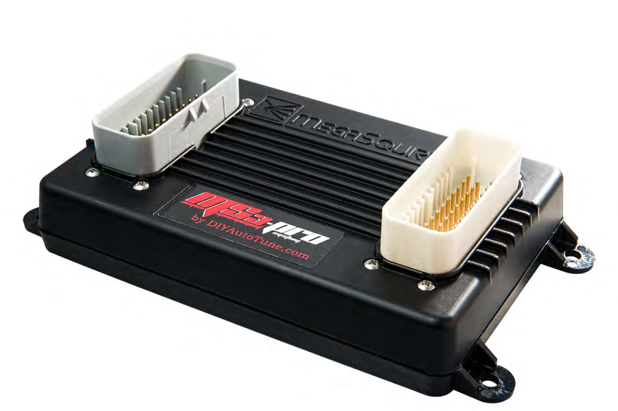
MS3Pro Gen1 is a MegaSquirt-family engine-management product. The first-generation MS3Pro is a packaged MS3-derived ECU. DIYAutoTune lists it as discontinued; distinguish it from EVO and Ultimate before using connector assignments. Model source.
Identification and software
Record the ECU label, processor generation, board revision, firmware and installed hardware modifications. Calibration software and firmware must match the hardware. DIYAutoTune software and firmware · Model-specific information.
Wiring and pinout
Use the matching model document and wiring or support reference; the manufacturer manual index distinguishes wire-in and vehicle-specific variants. Check connector orientation, wiring changes, fuse ratings and output configuration before connecting loads; matching cases or software families do not establish identical pin functions.
See the MegaSquirt and MS3Pro family guide. Sources reviewed 17 November 2026.
First-generation ECU connector pin assignments
The AMP EFI first-generation manual, version 1.210 for firmware 1.5.2 documents the two 35-way connectors below. The first-generation white connector carries serial signals at pins 17, 22 and 23, and differs from EVO. Confirm the hardware, connector face and firmware before wiring; see the manual for grounding and electrical limits.
White connector — 35 way
| Pin | Function in source |
|---|---|
| 1 | High current out 1 |
| 2 | High current out 2 |
| 3 | Injector out J |
| 4 | Injector out I |
| 5 | High current out 3 |
| 6 | CKP+ |
| 7 | Knock In 2 |
| 8 | 5V+ VREF out |
| 9 | TPS in |
| 10 | MAT in |
| 11 | CLT in |
| 12 | MAP in |
| 13 | Power ground |
| 14 | PWM / Idle Out 1 |
| 15 | CKP- |
| 16 | Logic ground * |
| 17 | RS232 ground ** |
| 18 | Sensor return |
| 19 | Analog in 1 |
| 20 | Analog in 2 |
| 21 | Analog in 3 |
| 22 | RS232 TX ** |
| 23 | RS232 RX ** |
| 24 | Tach out |
| 25 | O2 in |
| 26 | CMP+ |
| 27 | CMP- |
| 28 | Fuel pump relay out |
| 29 | PWM out 2 |
| 30 | PWM out 3 |
| 31 | Knock in 1 |
| 32 | Digital switched in 1 |
| 33 | CAN L |
| 34 | CAN H |
| 35 | 12V+ switched power in |
Gray connector — 35 way
| Pin | Function in source |
|---|---|
| 1 | Injector out A |
| 2 | Injector out B |
| 3 | Ground |
| 4 | Injector out C |
| 5 | Ground |
| 6 | Injector out D |
| 7 | Ground |
| 8 | Injector out E |
| 9 | Ground |
| 10 | Injector out F |
| 11 | Injector out G |
| 12 | Injector out H |
| 13 | Spark out G |
| 14 | Spark out E |
| 15 | Spark out C |
| 16 | Spark out H |
| 17 | Digital frequency in 2 |
| 18 | Ground |
| 19 | Digital switched 12V in |
| 20 | Digital switched in 2 |
| 21 | Digital frequency in 3 |
| 22 | USB power |
| 23 | USB ground |
| 24 | Spark out F |
| 25 | Spark out B |
| 26 | Spark out D |
| 27 | Spark out A |
| 28 | Digital frequency in 1 |
| 29 | Digital switched in 3 |
| 30 | Stepper IAC out 1B |
| 31 | Stepper IAC out 1A |
| 32 | Stepper IAC out 2A |
| 33 | Stepper IAC out 2B |
| 34 | USB D- |
| 35 | USB D+ |