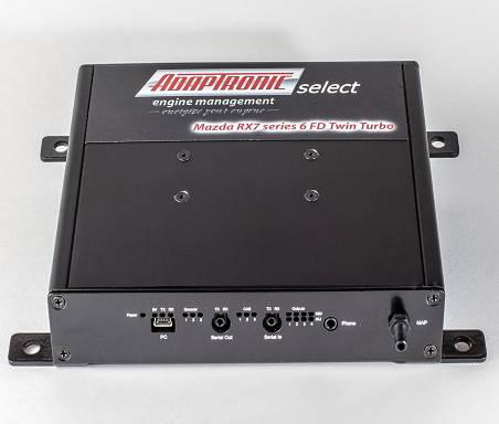
Adaptronic eSel021 is a Select-series vehicle plug-in programmable engine-management ECU. The surviving manufacturer guide identifies the intended application as Mazda RX-7 FD Series 6 13B REW twin turbo. Adaptronic eSel021 application and installation guide.
Identification and application
Confirm the case label and part number, original ECU and loom connector, engine, market and any vehicle-specific equipment against the guide before purchase or installation. Vehicle wiring can vary, and a shared plug shape does not establish pin compatibility.
Software and installation
The Select family uses Adaptronic WARI software, which is listed in Haltech’s legacy Adaptronic downloads archive. Use the matching eSel021 guide and application-specific basemap; the guide documents installation, configuration and pin references. A plug-in ECU still requires configuration and tuning for the actual engine and equipment.
Wiring and pinout
The manufacturer eSel021 guide contains the model and application-specific connector information. Positions and functions can change by application, and factory function and Adaptronic function are separate columns in the guide. The manufacturer connector table is transcribed below; verify the source and viewpoint before use.
Support and sources
Haltech states that Adaptronic operations ended in 2022. Refer to its Adaptronic notice and archived guides, and confirm current support and compatibility for used hardware. A verified product photograph for this exact part has not yet been added.
Manufacturer connector table
Transcribed from the model-specific Adaptronic installation guide linked above. The guide gives pin numbering from the loom side of the plug, looking into the ECU. A dash denotes a blank source cell. The source says NC is no connection in the factory loom and an empty Adaptronic column means no connection to the Adaptronic ECU. The first column includes the factory wire colour where documented.
| Factory pin / colour | Factory function | Adaptronic function | Installation notes |
|---|---|---|---|
| 4Z Lg | Injector (Rear Secondary) | Injector Output 4 | — |
| 4Y Lg/B | Injector (Rear Primary) | Injector Output 3 | — |
| 4X Lg/W | Injector (Front Secondary) | Injector Output 2 | — |
| 4W Lg/R | Injector (Front Primary) | Injector Output 1 | — |
| 4V L/Y | Turbo Pre Control Solenoid Valve | Aux Output 1 | — |
| 4U L/W | Wastegate Control Solenoid Valve | Aux Output 3 | — |
| 4T L/B | Charge Control Solenoid Valve | Charge Control Valve Output | Inverse of 4R and 4S. |
| 4S P | Charge Relief Solenoid Valve | Aux Output 4 | Linked to 4R. |
| 4R Y/L | Turbo Control Solenoid Valve | Aux Output 4 | Linked to 4S. |
| 4Q L/G | Idle Control Solenoid Valve | Aux Output 2 | — |
| 4P | AWS Solenoid Valve | — | — |
| 4O L/Y | EGR Solenoid Valve | — | — |
| 4N L/R | Secondary Air Switch Valve | PGND | — |
| 4M L/O | PRC Solenoid Valve | — | — |
| 4L B/Y | Oil Metering Pump 1 bar | Aux Output 7 bar | Inverse of 4J. |
| 4K B/Lg | Oil Metering Pump 2 bar | Aux Output 8 bar | Inverse of 4I. |
| 4J B/L | Oil Metering Pump 1 | Aux Output 7 | — |
| 4I B/O | Oil Metering Pump 2 | Aux Output 8 | — |
| 4H R | Crankshaft Sensor -ve | SGND | — |
| 4G W | Crank Pos Sensor G (1 tooth) +ve | CAS 2 input | — |
| 4F B/R | Split Air Bypass Solenoid Valve | — | — |
| 4E B | Crank Pos Sensor NE (12 tooth) +ve | CAS 1 input | — |
| 4D Br/B | Sensor Ground | SGND | — |
| 4C B | Chassis Ground | PGND | — |
| 4B B/W | Chassis Ground | PGND | — |
| 4A B/W | Chassis Ground | PGND | — |
| 3P Y/R | Secondary Air Bypass Valve | — | — |
| 3O B/R | Double Throttle Solenoid Valve | — | Left open in the documented three-throttle setup. |
| 3N L | Port Air Bypass Solenoid Valve | — | — |
| 3M W | Knock Sensor | Knock input | — |
| 3L G | Intake Air Temperature Senor | MAT input | — |
| 3K G/O | Relief 2 Solenoid Valve | — | — |
| 3J L/G | EGR Function Sensor | — | — |
| 3I Br/W | TPS, MAP, MOP 5V | TPS 5V | — |
| 3H G/Y | Purge Solenoid Valve | — | — |
| 3G B/G | TPS Full Range | TPS signal input | — |
| 3F G/R | TPS Narrow Range | — | — |
| 3E G/W | Coolant Temp Sensor | ECT | — |
| 3D W/L | Cooling Fan Relay | Aux Output 6 | — |
| 3C B | Oxygen Sensor Input | O2 signal Input | — |
| 3B Y | Electrical Load | Digital Input 8 | — |
| 3A G/B | Metering Oil Pump position sensor | Ext In | — |
| 2L W/G | Gear 2 detection | Digital Input 7 | Optional digital input for boost or launch control. |
| 2K V/W | Gear 1 detection | Digital Input 6 | Optional digital input for boost or launch control. |
| 2J Gy | Air Pump Relay | — | — |
| 2I O/L | Heat Hazard Sensor | — | — |
| 2H | — | SVSS2 | Optional front-right wheel speed. |
| 2G Lg/R | Auto Transmission | — | — |
| 2F B | Shorted to ground on Canadian cars | SVSS1 | Optional front-left speed or flex fuel. |
| 2E O/B | Auto Transmission | — | — |
| 2D Y/G | Auto Transmission | — | — |
| 2C L | Auto Transmission | — | — |
| 2B Y/L | Tachometer output | Tacho Out | Combined trailing-ignition 1 and 2 outputs. |
| 2A | — | MVSS2 input | Optional rear-right speed or flex fuel. |
| 1V(V) | — | — | — |
| 1U(U) L | Fuel Thermo Sensor | Aux Temp | Optional temperature logging input; not used for tuning. |
| 1T(T) L/R | Fuel Pump Relay | Aux Output 5 | — |
| 1S(S) G | Stoplight Switch | Digital Input 5 | Optional digital input for boost or launch control. |
| 1R(R) G/W | Neutral Switch | Digital Input 2 | — |
| 1Q(Q) L/O | Clutch Switch | Digital Input 1 | — |
| 1P(P) | — | — | — |
| 1O(O) G/Y | MAP Sensor signal | MAP signal input | — |
| 1N(N) L/Y | Steering Pressure Sensor | Digital Input 3 | — |
| 1M(M) G/R | Speedometer | MVSS1 | Optional rear-left wheel speed. |
| 1L(L) Y/B | A/C Relay | AC Relay Output | — |
| 1K(K) L/W | Fuel Pump Relay (Speed) | PGND | — |
| 1J(J) Br/B | Igniter Trailing Rear | Igniter Output 3 | — |
| 1I(I) Lg/Y | Data Link Connector | Igniter Output 4 | Optional rotor 2 leading ignition; diagnostic light-green/yellow wire; sacrifices pre-control output. |
| 1H(H) Lg | Igniter Leading | Igniter Output 1 | Direct-fire conversion: rotor 1 leading. |
| 1G(G) Br | Igniter Trailing Front | Igniter Output 2 | — |
| 1F(F) W/B | Data Link Connector | — | — |
| 1E(E) W | Refrigerant Pressure Switch | Digital Input 4 | — |
| 1D(D) W/R | Data Link Connector | CAS 3, for flex fuel | Diagnostic white/red wire. |
| 1C(C) B/R | Park/Neutral Switch (AT) / starter | — | — |
| 1B(B) B/W | Main Relay | +12 Ignition | — |
| 1A(A) L/R | Constant Power | Const 12V | Fused battery supply. |
Manufacturer photograph