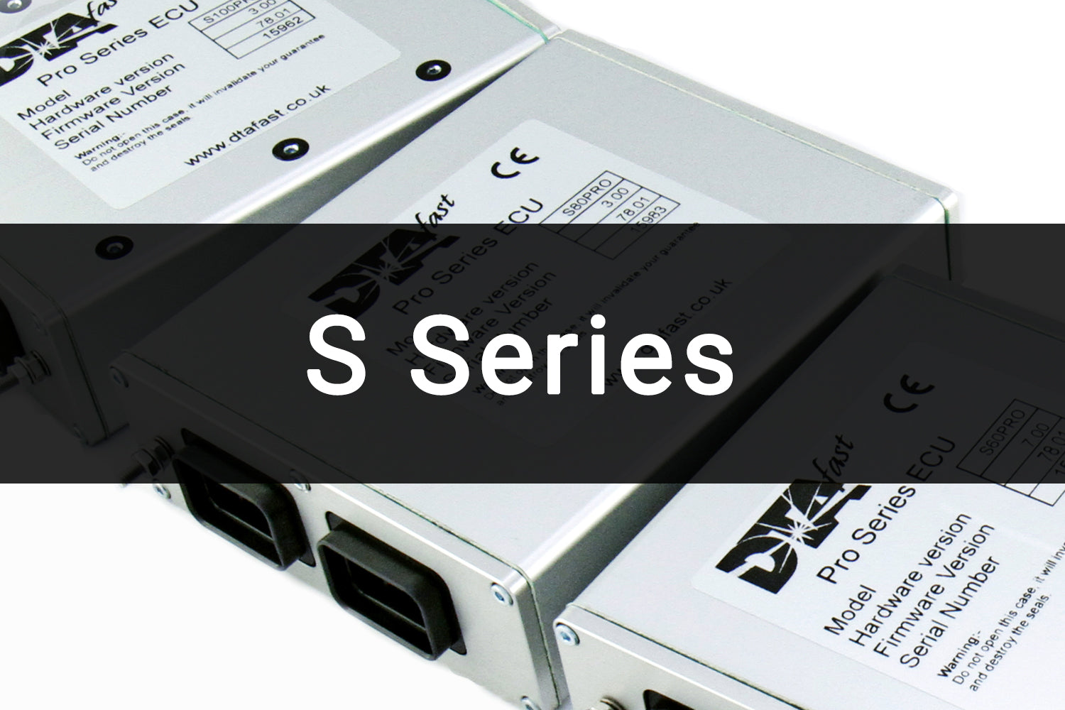
The DTAFast S40 Pro is an S-series programmable engine-management unit. Two injector drivers and two coil drivers; its feature matrix identifies no cam input. It is designed for semi-sequential four-cylinder fuel injection with wasted spark, and a related ignition-only variant is documented. DTAFast historical S-series feature matrix.
Hardware and operation
The manufacturer diagram is labelled S40PRO, drawn from the pin-insertion side and specifies firmware V77.00 or later. Injector 2 can share its output with idle control; exact use depends on configuration. Confirm the complete ECU label and revision; similarly named S-series units are separate records, and S-series capability differs from T-series. Record the number of injectors, coil arrangement, cam triggers and assigned auxiliary outputs before selecting a calibration.
Wiring and pinout
DTAFast S40 connector pinout and wiring gives connector views, supplies, grounds, sensor and actuator examples. Consult the documented firmware and circuit protection conditions; identify connector keyways and view direction before counting pins. A shared input or output can perform only the function assigned to it.
Software and additional references
The DTAFast S-series Pro manual describes DTASwin calibration software, data logging and model-specific settings. DTAFast S60 Pro product sheet provides an example of output and engine configuration limits. See the DTAFast model family for other ECUs.
S40 Pro pinout — manufacturer diagram
The single 34-way plug carries power and sensor connections. Both tables refer to the same connector. DTAFast's S40 Pro wiring diagram is dated 18 November 2014 and specifies firmware V77.00 or later. Both connector views are drawn from the pin-insertion side. These tables transcribe the functions shown; unlisted pins are not established as unused. Slash-separated labels are alternatives or configuration-dependent functions.
Power connections
| Pin | Documented function |
|---|---|
| 1 | Aux 4 / fuel pump relay |
| 3 | Coil 1 |
| 6 | Coil 2 |
| 8 | Injector 1 |
| 9 | Injector 2 or idle valve |
| 10 | Aux 5 / shift light / VTEC / dump valve |
| 13, 14 | Power grounds |
| 18 | Aux 2 / fan / turbo valve |
| 26 | Aux 6 / tacho |
| 31 | Fused 12 V supply |
Sensor connections
| Pin | Documented function |
|---|---|
| 11 | Shift cut / E85 sensor / shaft speed / air-con signal |
| 12 | Undriven wheel speed, Hall effect |
| 16 | CAN high |
| 17 | CAN low |
| 19 | Crank VR |
| 21 | Lambda signal |
| 22 | Throttle potentiometer |
| 23 | Analogue 2 / oil pressure |
| 24 | Water temperature |
| 25 | Analogue 1 / oil temperature / launch RPM |
| 27 | 5 V output |
| 28, 29 | Sensor ground |
| 30 | Launch button |
| 32 | Air temperature |
| 33 | Analogue 3 / fuel pressure / gear |
| 34 | MAP |
The source diagram shows the 20 A fused supply and notes that injector 2 is shared with the idle-valve function. Check the exact model, keying, orientation, calibration and electrical ratings in the original diagram before wiring.