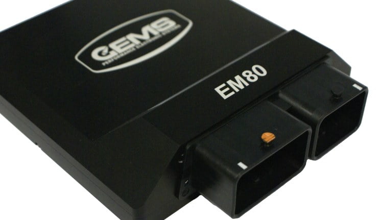
GEMS EM80: A compact standalone system for up to eight cylinders with gearshift, electronic throttle and high-speed logging. Manufacturer source.
Hardware and control
The manufacturer lists eight ignition and eight injector drivers, one wideband input, two CAN buses, 256 MB logging and an 80-way connector. Compare the detailed datasheet with the product page: the product page calls the half bridges 6 A, while rev 24 states 5 A; confirm ratings for the particular unit. GEMS model information.
GEMS systems use GWv4 configuration, with the required ECU definition and licence; software options and custom builds can differ. Record the label, hardware and firmware and confirm connected devices against the matching documentation. GWv4 manual.
Connector 1 pinout — 102987 rev 24
The manufacturer technical specification identifies connector 1 as the 32-position mating connector; use its drawing and cavity markings for orientation, verify current limits and shared input functions. These positions apply only to this specific model and document revision.
| Pin | Function in source |
|---|---|
| A1 | Knock input + |
| B1 | Knock input − |
| C1 | Active throttle feedback 2 |
| D1 | Active throttle feedback 1 |
| E1 | MAF input |
| F1 | Coolant temperature input |
| G1 | Bridge driver A+ |
| H1 | Ignition coil driver 8 |
| A2 | CAN 2 low |
| B2 | CAN 2 high |
| C2 | Active throttle feedback 3 |
| D2 | Active throttle feedback 4 |
| E2 | 5 V sensor supply 1 |
| F2 | Sensor ground |
| G2 | Bridge driver A− |
| H2 | Ignition coil driver 7 |
| A3 | CAN 1 low |
| B3 | CAN 1 high |
| C3 | MAP input |
| D3 | Lambda input 1, narrowband |
| E3 | Lambda input 2, narrowband |
| F3 | Sensor ground |
| G3 | Ignition coil driver 6 |
| H3 | Ignition coil driver 5 |
| A4 | Ethernet RX− |
| B4 | Ethernet RX+ |
| C4 | Ethernet TX− |
| D4 | Ethernet TX+ |
| E4 | Differential analogue input − |
| F4 | Differential analogue input + |
| G4 | Secondary 12 V supply / ignition switch |
| H4 | Power return |
Connector 2 pinout — 102987 rev 24
The GEMS EM80 rev 24 datasheet identifies connector 2 as the 48-position mating connector. Coil drivers 1 and 3, and 2 and 4, are labelled as multiplexed pairs. The EM80-M datasheet assigns different coil-driver names at L2, M2 and M3; confirm the model and software. See the original for software codes, electrical limits, connector orientation and notes.
| Pin | Function in source |
|---|---|
| A1 | PWM driver 3 |
| B1 | PWM driver 4 |
| C1 | Fuel injector driver 1 |
| D1 | Fuel injector driver 2 |
| E1 | Fuel injector driver 3 |
| F1 | Fuel injector driver 4 |
| G1 | Fuel injector driver 5 |
| H1 | Fuel injector driver 6 |
| J1 | Fuel injector driver 7 |
| K1 | Fuel injector driver 8 |
| L1 | Main 12 V supply |
| M1 | Power return |
| A2 | 5 V sensor supply 3 |
| B2 | Timing input 12 |
| C2 | Timing input 11 |
| D2 | Timing input 10 |
| E2 | Timing input 9 |
| F2 | Timing ground |
| G2 | Wideband lambda 1 |
| H2 | Wideband lambda 2 |
| J2 | Wideband lambda 3 |
| K2 | Wideband lambda 4 |
| L2 | Ignition coil driver 2 |
| M2 | Ignition coil driver 4 |
| A3 | Sensor ground |
| B3 | Air inlet temperature input |
| C3 | Accelerator pedal input 1 |
| D3 | Accelerator pedal input 2 |
| E3 | Timing input 1 |
| F3 | Timing input 2 |
| G3 | Timing input 3 |
| H3 | Timing input 4 |
| J3 | 5 V sensor supply 2 |
| K3 | Wideband lambda heater |
| L3 | Bridge driver B− |
| M3 | Ignition coil driver 3 |
| A4 | PWM driver 7 |
| B4 | PWM driver 8 |
| C4 | PWM low-side driver 15 |
| D4 | PWM low-side driver 16 |
| E4 | PWM low-side driver 14 |
| F4 | PWM low-side driver 13 |
| G4 | PWM low-side driver 12 |
| H4 | PWM low-side driver 11 |
| J4 | PWM low-side driver 10 |
| K4 | PWM low-side driver 9 |
| L4 | Bridge driver B+ |
| M4 | Ignition coil driver 1 |
Some functions can be reassigned or shared; match the actual hardware and calibration.
Further references
- GEMS EM80 manufacturer source
- Model-specific technical and wiring specification
- GEMS software and downloads
- GEMS manufacturer overview
Sources reviewed 17 November 2026.