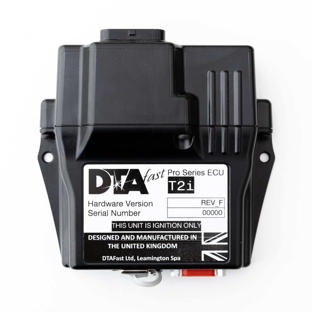
Ignition-only controller for carburetted or historic engines; supports distributor ignition on up to 12 cylinders or wasted spark on up to four. It does not control fuel injectors. DTAFast T2i product information.
Features and application
Wideband lambda monitoring and logging, launch, closed-loop flat shift, boost and electric fuel-pump relay control are listed by DTAFast. The fuel pump can be commanded off when the engine stops. All T-series units use the T-Series PC software; DTAFast describes configurable inputs and outputs, integrated Bosch wideband measurement, logging, firmware updates and a built-in trigger oscilloscope. Available functions and channel limits depend on the exact model and firmware. Manufacturer specification.
Identification and wiring
Identify the printed model including any “+” or “i” suffix, hardware revision, connector and firmware before allocating pins. Configurable functions may differ from defaults. Manufacturer T2i wiring diagram and connector pinout contains connector orientation, cavity functions, power, earth and sensor examples. Follow its fuse and load requirements; do not interchange pin numbering with another T-series controller.
Complete connector pin assignments
The following tables reproduce the pin positions and labels in the DTAFast T2I wiring diagram. The manufacturer's drawing shows the pin-insertion side. A dash is shown where the drawing has no function assigned; analogue, digital and PWM functions may be configured in software. Verify actual hardware revision, wiring and electrical limits against the source.
Connector 1 — pinout version 1.03
| Pin | Function in manufacturer diagram |
|---|---|
| 1 | PWM 1 |
| 2 | Lambda Nernst Voltage |
| 3 | Coil 1 |
| 4 | Lambda VGND |
| 5 | Lambda Pump Current |
| 6 | Coil 2 |
| 7 | Lambda Trim Resistor |
| 8 | - |
| 9 | - |
| 10 | PWM 2 |
| 11 | Digital 1 |
| 12 | Wheel 1 |
| 13 | Power Ground 1 |
| 14 | Power Ground 2 |
| 15 | Lambda Heater Negative |
| 16 | CAN High |
| 17 | CAN Low |
| 18 | PWM 3 |
| 19 | Crank |
| 20 | Analogue 1 |
| 21 | Permanent 12v |
| 22 | Analogue 2 |
| 23 | Analogue 3 |
| 24 | Thermistor 1 |
| 25 | Analogue 4 |
| 26 | PWM 4 |
| 27 | 5v Out |
| 28 | Sensor Ground |
| 29 | Sensor Ground |
| 30 | Digital 2 |
| 31 | Ignition 12v In |
| 32 | Thermistor 2 |
| 33 | Analogue 5 |
| 34 | Analogue 6 |
Software and related information
DTAFast provides model-specific wiring diagrams, firmware, manuals and PC software via its downloads section. Capture the existing calibration and firmware identifiers before making changes. See the DTAFast family overview for earlier S and E series models.