The Adaptronic eMod005 is an application-specific plug-in programmable engine-management ECU. Haltech's surviving Adaptronic downloads archive identifies the application as Nissan S13 180SX/Silvia redtop, S13 blacktop Type X, S14a 64-pin and S15. The part number identifies a family of applications, not an unconditional guarantee of vehicle compatibility. Haltech Adaptronic downloads archive.
Application and installation
Identify the vehicle, engine, connector and wiring variation before installation. Plug-in installation can still require additional sensor and actuator wiring, and tuning to suit the specific engine. The manufacturer archive provides the Adaptronic plug-in ECU startup guide and EUGENE tuning software.
Model-specific pinout
In the eMod005 section of the manufacturer download archive, find: separate S13 redtop, S13 Type X, S14a 64-pin and S15 pinout ZIP files. Open the matching vehicle-specific diagram; connector or pin functions cannot safely be inferred from a different eMod or a different application. The archive also lists the following basemap resource: separate S13, Type X, S14a and S15 basemaps.
Documentation limits
Complete channel counts and additional variants have not been independently verified for this exact model. Haltech's Adaptronic notice records the end of Adaptronic operations in 2022; use the archived documentation and confirm present support before purchasing a used ECU.
Manufacturer connector tables and photographs
Illustrations: Adaptronic, preserved in the Haltech Adaptronic archive, reproduced with permission. Each manufacturer sheet includes a product photograph, connector orientation, factory function, Adaptronic function and manufacturer comments.
These are separate vehicle pinouts, viewed looking into the ECU; do not interchange application-specific factory functions.
S13 180SX/Silvia redtop SR20DET — open the full-size manufacturer connector diagram and table.
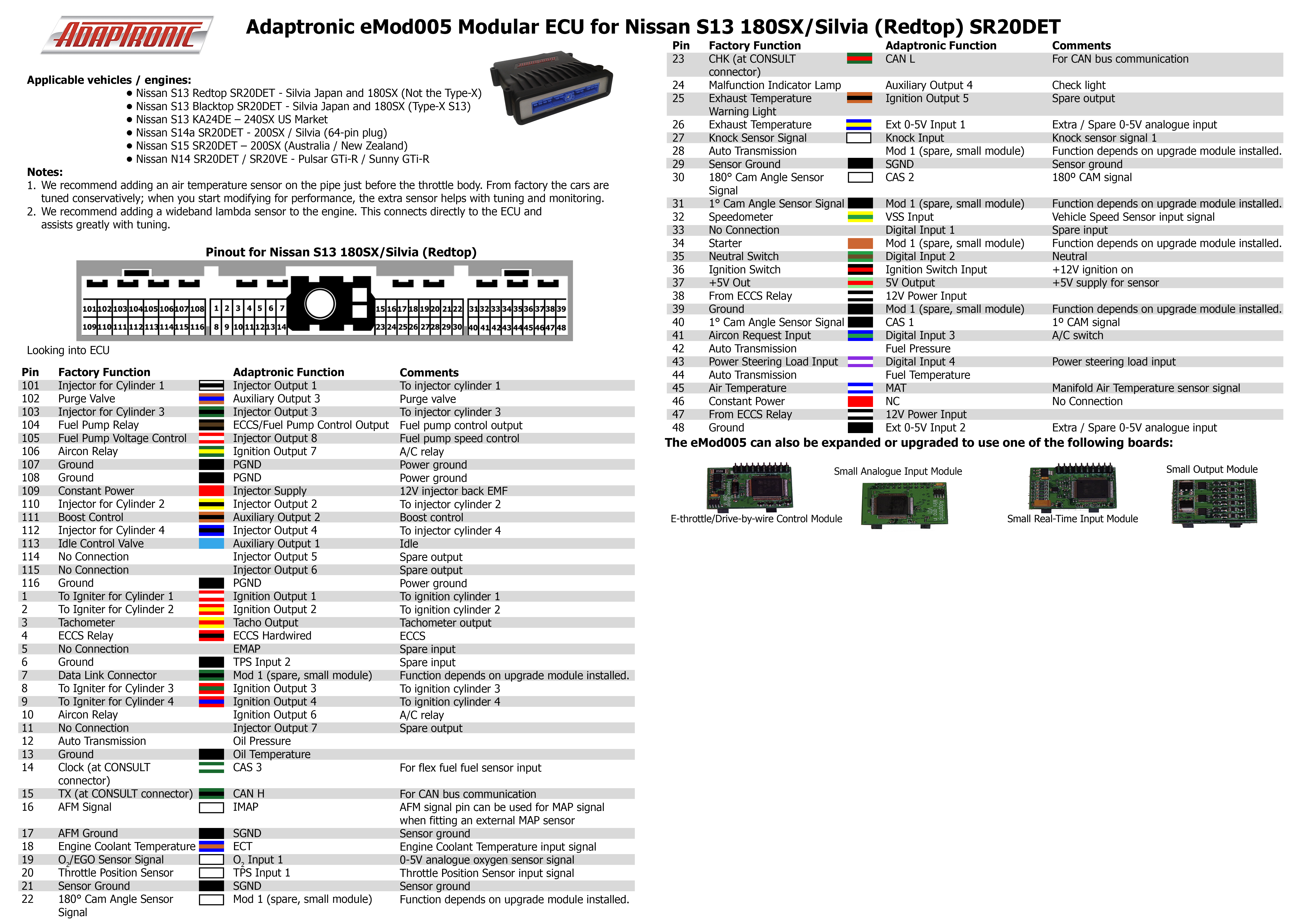
S13 180SX/Silvia blacktop Type X — open the full-size manufacturer connector diagram and table.

S14a 200SX/Silvia 64-pin — open the full-size manufacturer connector diagram and table.
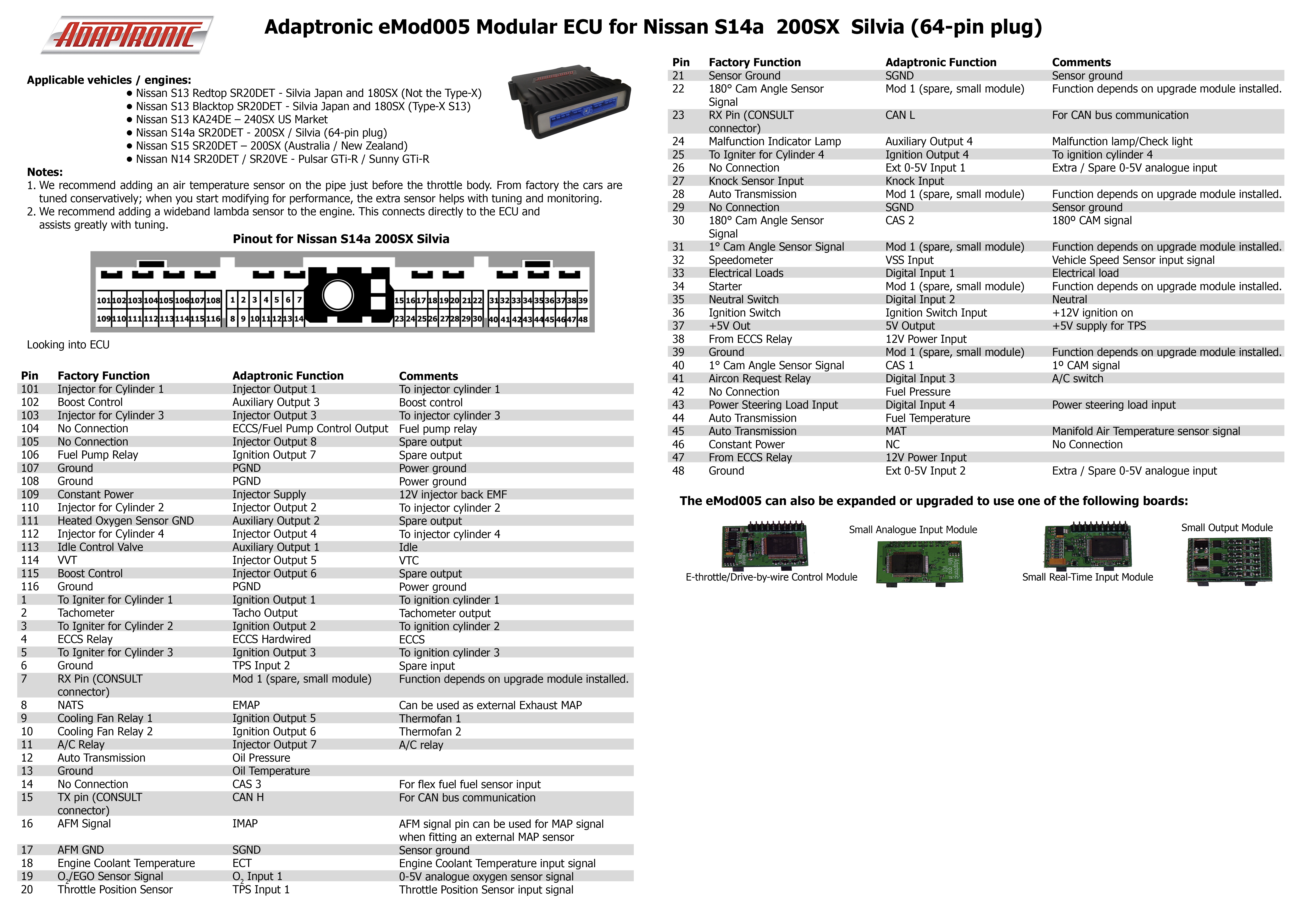
S15 200SX/Silvia — connector table
The S15 table below transcribes the separate manufacturer S15 pinout ZIP. The sheet describes the S15 SR20DET 200SX Australia/New Zealand application. Factory and Adaptronic functions are separate columns; Mod 1 depends on the installed upgrade module. Refer to the original sheet for wire colours and manufacturer comments.
| Pin | Factory function | Adaptronic function |
|---|---|---|
| 101 | Injector cylinder 1 | Injector output 1 |
| 102 | Boost control | Auxiliary output 3 |
| 103 | Injector cylinder 3 | Injector output 3 |
| 104 | No connection | ECCS/fuel pump control output |
| 105 | Intake valve timing control solenoid | Injector output 8 |
| 106 | Fuel pump relay | Ignition output 7 |
| 107 | Ground | PGND |
| 108 | Ground | PGND |
| 109 | Constant power | Injector supply |
| 110 | Injector cylinder 2 | Injector output 2 |
| 111 | Heated oxygen sensor ground | Auxiliary output 2 |
| 112 | Injector cylinder 4 | Injector output 4 |
| 113 | Idle control valve | Auxiliary output 1 |
| 114 | VVT | Injector output 5 |
| 115 | Boost control | Injector output 6 |
| 116 | Ground | PGND |
| 1 | Igniter cylinder 1 | Ignition output 1 |
| 2 | Tachometer | Tacho output |
| 3 | Igniter cylinder 2 | Ignition output 2 |
| 4 | ECCS relay | ECCS hardwired |
| 5 | Igniter cylinder 3 | Ignition output 3 |
| 6 | Ground | TPS input 2 |
| 7 | CONSULT RX pin | Mod 1 |
| 8 | NATS | EMAP |
| 9 | Cooling fan relay 1 | Ignition output 5 |
| 10 | Cooling fan relay 2 | Ignition output 6 |
| 11 | A/C relay | Injector output 7 |
| 12 | Automatic transmission | Oil pressure |
| 13 | Ground | Oil temperature |
| 14 | No connection | CAS 3 |
| 15 | CONSULT TX pin | CAN H |
| 16 | AFM signal | IMAP |
| 17 | AFM ground | SGND |
| 18 | Engine coolant temperature | ECT |
| 19 | Oxygen sensor | O2 input 1 |
| 20 | Throttle position sensor | TPS input 1 |
| 21 | Sensor ground | SGND |
| 22 | Cam angle sensor 180° | Mod 1 |
| 23 | CONSULT RX pin | CAN L |
| 24 | Malfunction indicator lamp | Auxiliary output 4 |
| 25 | Igniter cylinder 4 | Ignition output 4 |
| 26 | No connection | External 0–5 V input 1 |
| 27 | Knock sensor input | Knock input |
| 28 | Automatic transmission | Mod 1 |
| 29 | No connection | SGND |
| 30 | Cam angle sensor 180° | CAS 2 |
| 31 | Cam angle sensor 1° | Mod 1 |
| 32 | Speedometer | VSS input |
| 33 | Electrical loads | Digital input 1 |
| 34 | Starter | Mod 1 |
| 35 | Neutral switch | Digital input 2 |
| 36 | Ignition switch | Ignition switch input |
| 37 | +5 V output | 5 V output |
| 38 | From ECCS relay | 12 V power input |
| 39 | Ground | Mod 1 |
| 40 | Cam angle sensor 1° | CAS 1 |
| 41 | Air conditioning request | Digital input 3 |
| 42 | No connection | Fuel pressure |
| 43 | Power steering load | Digital input 4 |
| 44 | Automatic transmission | Fuel temperature |
| 45 | Automatic transmission | MAT |
| 46 | Constant power | NC |
| 47 | From ECCS relay | 12 V power input |
| 48 | Ground | External 0–5 V input 2 |
Nissan S15 200SX Silvia manufacturer illustration
Open the scaled manufacturer pinout and product photograph. The image was proportionally reduced from the Adaptronic original to fit the wiki; source: Haltech's Adaptronic archive. Adaptronic illustration reproduced with permission. Consult the linked original ZIP for the unscaled source.
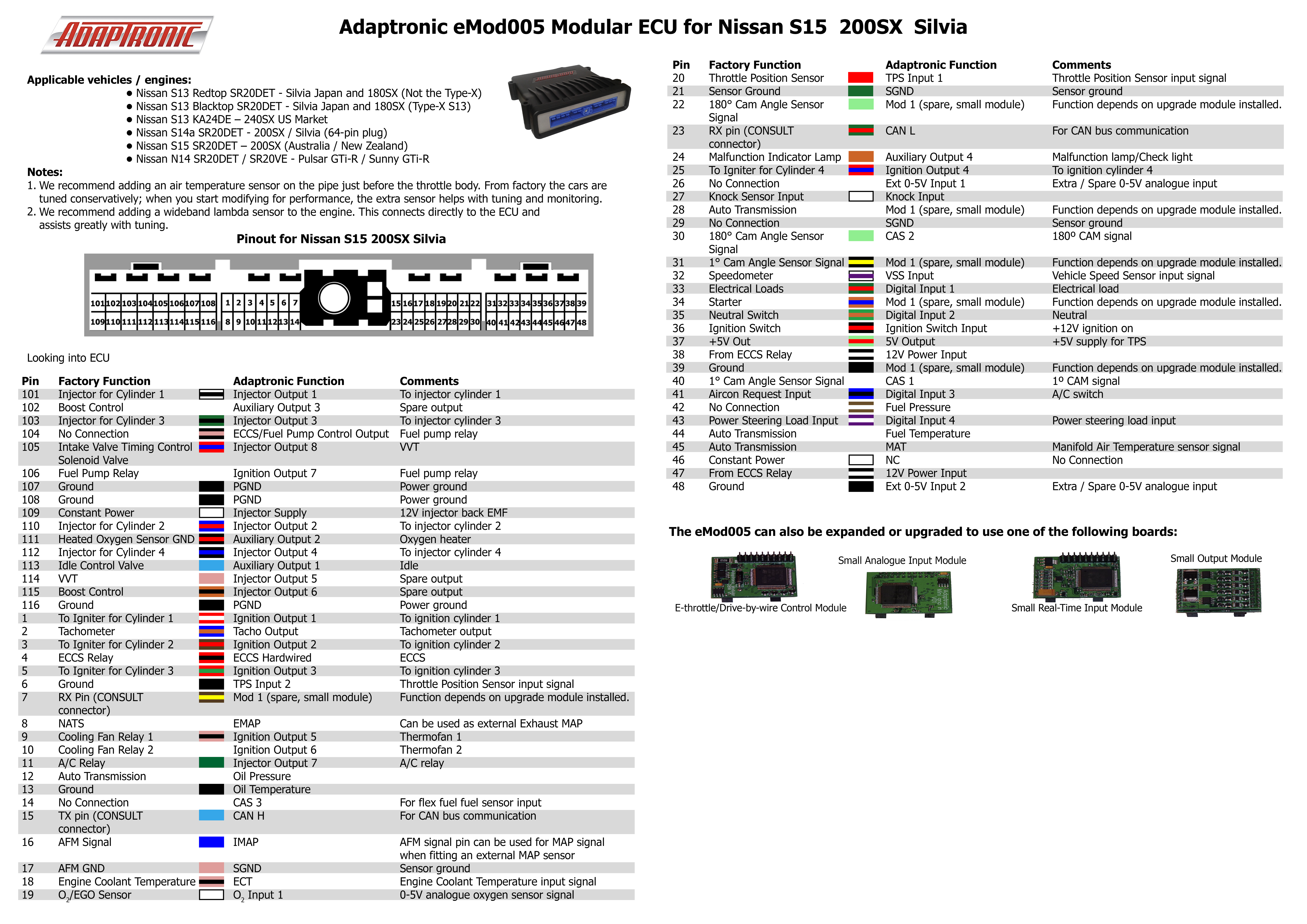
Connector pinout
A structured, redrawn pin diagram of the S15 connector is available at Adaptronic eMod005 connector pinout. Diagram redrawn by Tuning Wiki from the Adaptronic S15 pinout sheet.