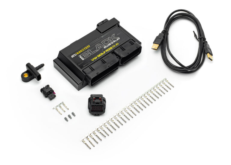
ECUMaster separately identifies a Volkswagen R32 VR6 BUB EMU Black plug-in ECU, distinct from its BFH version. Confirm exact engine code, original hardware and connector before applying the manufacturer's BUB documentation. Model source · ECUMaster plug-in catalogue.
Wiring and pinout
The official BUB pinout spreadsheet v2 provides factory and extension connector functions. The following reproduce the assigned terminals from that BUB-labelled document; use its connector drawing for the exact unit and orientation. Manufacturer model-specific document.
Factory connector — source-listed assignments
The manufacturer's spreadsheet lists the following populated or assigned terminal numbers. Positions not listed in that source are not identified here as unused. PPS means pedal position sensor; DBW means drive-by-wire.
| Terminal | Vehicle function | EMU input / output in source |
|---|---|---|
| 1 | Power ground | Power ground |
| 2 | Power ground | Power ground |
| 3 | Main relay +12 V | |
| 4 | Second lambda heater | Internal WBO-to-CAN module |
| 5 | First lambda heater | WBO heater |
| 12 | Second lambda VGND | Internal WBO-to-CAN module VGND |
| 13 | Second lambda VS | Internal WBO-to-CAN module VS |
| 14 | Second lambda RCAL | Internal WBO-to-CAN module RCAL |
| 15 | Second lambda IP | Internal WBO-to-CAN module IP |
| 21 | Ignition +12 V | Ignition switch +12 V |
| 22 | Vacuum pump relay | H-bridge 2 B |
| 23 | Main relay | AUX 6 |
| 26 | Intake air temperature | IAT |
| 27 | IAT sensor ground | Sensor ground |
| 33 | PPS sensor ground | Sensor ground |
| 34 | PPS inverted | Analogue input 1 |
| 35 | PPS positive | TPS input |
| 36 | PPS sensor ground | Sensor ground |
| 37 | A/C engine speed signal | H-bridge |
| 39 | Clutch switch | Analogue input 5 |
| 41 | A/C signal | Analogue input 6 |
| 44 | Crankcase breather | AUX 4 |
| 51 | First lambda VGND | WBO VGND |
| 52 | First lambda IP | WBO IP |
| 55 | Brake switch | Analogue input 4 |
| 58 | CAN low | CAN low |
| 60 | CAN high | CAN high |
| 65 | AUX relay control | AUX 6 |
| 66 | BUB radiator fan control | AUX 5 |
| 70 | First lambda VS | WBO VS |
| 71 | First lambda RCAL | WBO Rcal |
| 72 | PPS +5 V | 5 V reference |
| 73 | PPS +5 V | 5 V reference |
| 82 | Crankshaft sensor | Primary trigger |
| 83 | DBW sensor ground | Sensor ground |
| 84 | DBW position sensor | Analogue 2 |
| 86 | Camshaft sensor | Secondary trigger |
| 87 | Camshaft sensor | Cam 2 |
| 88 | Injector 3 | Injector 3 |
| 89 | Injector 6 | Injector 6 |
| 90 | DBW sensor ground | Sensor ground |
| 91 | DBW +5 V | 5 V reference |
| 92 | DBW position sensor inverted | Analogue 3 |
| 93 | Coolant temperature sensor | CLT |
| 94 | Ignition coil 3 | Ignition coil 3 |
| 95 | Ignition coil 6 | Ignition coil 6 |
| 96 | Injector 1 | Injector 1 |
| 97 | Injector 5 | Injector 5 |
| 98 | CAM sensors +5 V | 5 V reference |
| 99 | Knock sensor ground | Sensor ground |
| 102 | Ignition coil 1 | Ignition coil 1 |
| 103 | Ignition coil 5 | Ignition coil 5 |
| 106 | Knock sensor 1 | Knock sensor 1 |
| 107 | Knock sensor 2 | Knock sensor 2 |
| 108 | Crank, coolant and knock sensor ground | Sensor ground |
| 110 | Ignition coil 2 | Ignition coil 2 |
| 111 | Ignition coil 4 | Ignition coil 4 |
| 112 | Injector 2 | Injector 2 |
| 113 | Injector 4 | Injector 4 |
| 115 | Intake variable valve solenoid | AUX 2 |
| 117 | DBW motor − | H-bridge 1 B |
| 118 | DBW motor + | H-bridge 1 A |
| 120 | Exhaust variable valve solenoid | AUX 1 |
| 121 | Intake variable-volume solenoid | AUX 3 |
Additional connector
| Terminal | Manufacturer function |
|---|---|
| 1 | Main relay +12 V |
| 2 | Power ground |
| 3 | CAN H |
| 4 | CAN L |
| 5 | RS232 TXD |
| 6 | RS232 RXD |
| 7 | Flex fuel input |
| 8 | +5 V reference |
| 9 | MAP sensor input |
| 10 | Analogue ground |
| 11 | EGT 2 input |
| 12 | Analogue ground |
| 13 | EGT 1 input |
| 14 | Analogue ground |
| 15 | MUX switch 3 input |
| 16 | Analogue ground |
| 17 | MUX switch 2 input |
| 18 | Analogue ground |
| 19 | MUX switch 1 input |
| 20 | +5 V reference |
| 21 | +5 V reference |
| 22 | +5 V reference |
| 23 | Analogue ground |
| 24 | Analogue ground |
| 25 | Analogue ground |
| 26 | Analogue ground |
Calibration and fitment checks
Record the engine code, ECU label and hardware, factory wiring and software version. The manufacturer provides software, available application notes and base maps; a base map is a starting point requiring checks of sensor readings, throttle operation, injector and ignition settings, trigger timing and engine calibration. Do not transfer universal EMU Black pin numbers or another plug-in's auxiliary connector assignments to this unit.
See the EMU Black model page and manufacturer index.