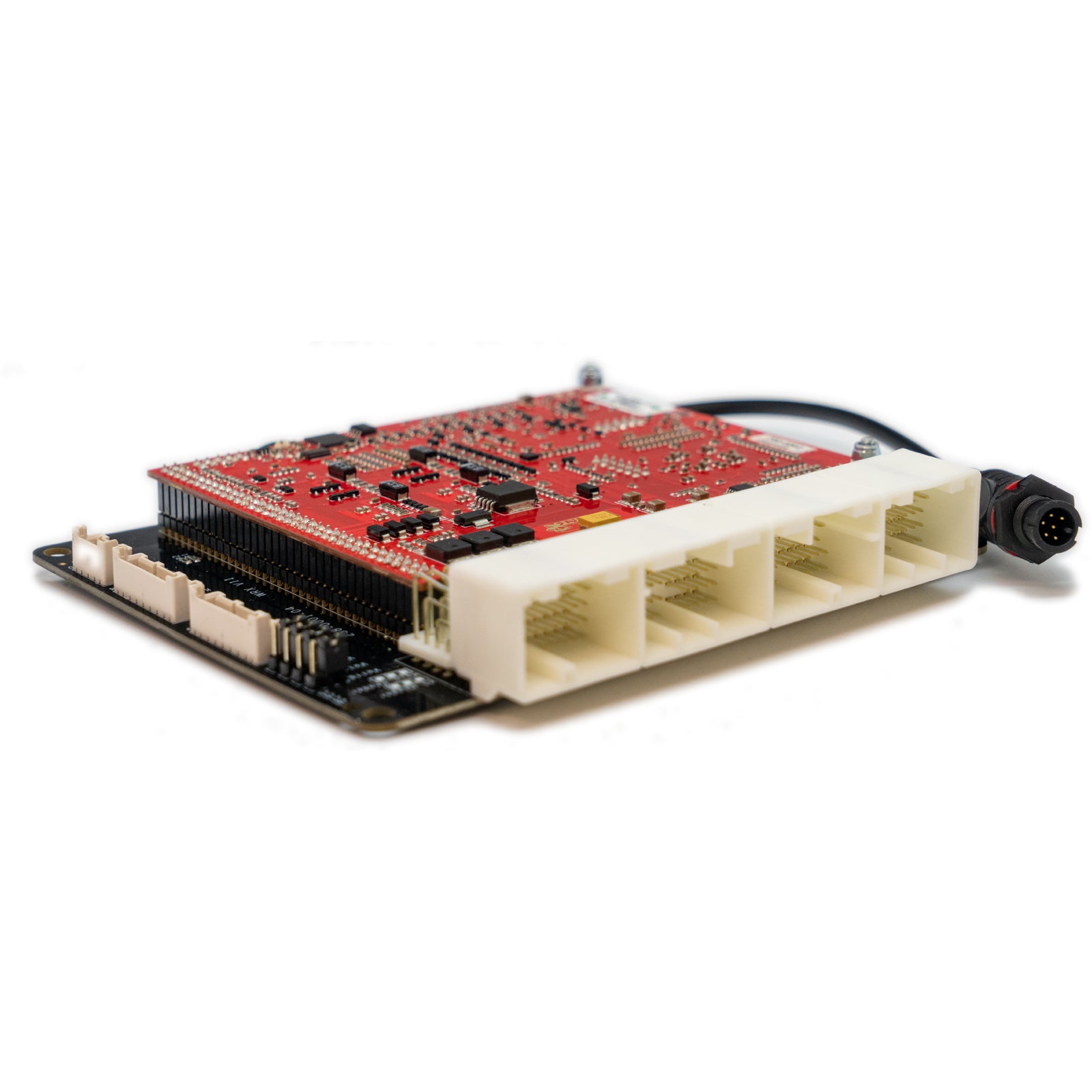
Link G4X WRX11X is a vehicle-specific programmable plug-in ECU for the Subaru WRX version 11; international and US versions must be checked application listed in Link's model-specific manuals index. It is an application board, rather than the universal wire-in ECU. Check the exact vehicle, market, engine, original ECU and board part number against the manufacturer's WRX11X installation manual.
Identification and installation
Record the Link model label and revision, donor factory ECU connector and car's engine and year. Plug-in boards connect to particular factory-harness layouts; the family or vehicle name alone does not establish every model-year or transmission combination. The manufacturer manual gives the supported application and any installation or configuration notes for this board.
G4X plug-in platforms offer configurable fuel and ignition control but available channels and features depend on the original header and board. The G4X plug-in general specifications are conditional on the particular application and do not mean every input is brought out to the factory harness.
Pinout and tuning
The WRX11X installation manual is the model-specific source for board pinouts, expansion connections, electrical cautions and startup configuration. Use its connector orientation and the exact board version; do not copy a wire-in ECU pinout onto a factory harness. PCLink and manual downloads; Link manufacturer overview.
Manufacturer connector schedules
From Link's WRX11 installation manual. Link describes the pinout view as looking into the ECU from the wire side. A dash reproduces an unspecified source field; nc is Link's label. Confirm the vehicle, market and board revision before use.
Link publishes separate WRX11 and WRX11 USDM pinouts, reproduced separately below. Analog inputs 6 and 11 and ignition 8 have pull-ups; the USDM and non-USDM boards expose different staged-injection outputs. CAN 2 is connected to the vehicle harness.
Factory main header: WRX11
| Factory pin | Link ECU channel | Factory function |
|---|---|---|
| A1 | nc | — |
| C7 | nc | — |
| A2 | nc | — |
| C8 | nc | — |
| A3 | nc | — |
| C9 | Ignition 6 (Aux) | AC Relay |
| A4 | An Temp 3 | IAT |
| C10 | nc | Alternator Control |
| A5 | Ground | — |
| C11 | Aux 11 | CE Light |
| A6 | An Volt 1 | MAP |
| C12 | Aux 6 | Fuel Pump Speed |
| A7 | +14V | ECU Power |
| C13 | nc | — |
| A8 | nc | — |
| C14 | Ground | — |
| A9 | nc | — |
| C15 | Ground | — |
| A10 | nc | — |
| C16 | nc | — |
| A11 | DI 1 | R/H Intake Cam Sensor |
| C17 | nc | — |
| A12 | DI 3 | R/H Exhaust Cam Sensor |
| C18 | Ignition 7 (Aux) | Sub Fan Relay |
| A13 | Trig 1 | Crank Sensor |
| C19 | nc | Secondary Air Valve |
| A14 | Ground (Crank Sensor) | — |
| C20 | Aux 12 | Starter Relay |
| A15 | Knock 1 | Knock Sensor |
| C21 | Aux 13 | E-Throttle Relay |
| A16 | An Volt 4 | Left TGV Pos (Jumper dependent) |
| C22 | Ignition 8 (Aux) | Tacho |
| A17 | nc | — |
| C23 | Main Relay Control | Triggered by B19 |
| A18 | An Volt 2 | TPS (Main) |
| C24 | DI 7 | AC Request (2007- 2011) |
| A19 | +5V Out | — |
| C25 | DI 4 | Clutch Sw |
| A20 | nc | — |
| C26 | nc | — |
| A21 | Trig 2 | L/H Intake Cam Sensor |
| C27 | CAN2 H | — |
| A22 | Ground (Cam Sensor) | — |
| C28 | nc | — |
| A23 | nc | — |
| C29 | Ignition 5 (Aux) | Main Fan Relay |
| A24 | Ground (Crank Shield) | — |
| C30 | nc | — |
| A25 | Ground (Knock Shield) | — |
| C31 | DI 9 | Neutral Sw |
| A26 | An Volt 5 | Right TGV Pos (Jumper dependent) |
| C32 | DI 8 | 2nd Start Signal |
| A27 | nc | — |
| C33 | nc | — |
| A28 | An Volt 3 | TPS (Sub) |
| C34 | nc | — |
| A29 | Ground | — |
| C35 | CAN2 L | — |
| A30 | nc | — |
| A31 | DI 2 | L/H Exhaust Cam Sensor |
| D1 | Ground | — |
| A32 | nc | — |
| D2 | Ground | — |
| A33 | An Volt 6 | Power Steer Sw |
| D3 | Ground | — |
| A34 | An Temp 1 | ECT |
| D4 | Aux 9 | E-Throttle Motor + |
| D5 | Aux 10 | E-Throttle Motor - |
| B1 | Ground (O2 Shield) | — |
| D6 | Ground (Ignition) | — |
| B2 | +14V | ECU Power |
| D7 | Ground | — |
| B3 | nc | — |
| D8 | Injector 1 | Injection |
| B4 | An Volt 7 | Rear O2 Signal (Jumper dependent) |
| D9 | Injector 2 | Injection |
| B5 | nc | Constant +12V |
| D10 | Injector 3 | Injection |
| B6 | nc | — |
| D11 | Injector 4 | Injection |
| B7 | nc | — |
| D12 | Linked to Pin D23 | L/H TGV Motor + |
| B8 | nc | Front O2 Signal - |
| D13 | Aux 8 | L/H TGV Motor - |
| B9 | nc | Front O2 Signal + |
| D14 | Aux 1 | L/H Intake AVCS Solenoid |
| B10 | nc | — |
| D15 | +14V Out | L/H Intake AVCS Solenoid |
| B11 | nc | — |
| D16 | Aux 2 | R/H Intake AVCS Solenoid |
| B12 | DI 10 | Cruise Main Sw |
| D17 | +14V Out | R/H Intake AVCS Solenoid |
| B13 | DI 6 | Start Signal |
| D18 | Ignition 1 | Ignition |
| B14 | nc | — |
| D19 | Ignition 2 | Ignition |
| B15 | nc | — |
| D20 | Ignition 3 | Ignition |
| B16 | nc | — |
| D21 | Ignition 4 | Ignition |
| B17 | nc | — |
| D22 | Aux 7 | R/H TGV Motor + |
| B18 | An Temp 2 | MAF Temp |
| D23 | Linked to Pin D12 | R/H TGV Motor - |
| B19 | Ignition Sw | Used to Control Main Relay |
| D24 | Aux 4 | R/H Exhaust AVCS Solenoid |
| B20 | DI 5 | Brake Sw NC |
| D25 | +14V Out | R/H Exhaust AVCS Solenoid |
| B21 | +5V Out (APS Main) | — |
| D26 | Ground | — |
| B22 | +5V Out (APS Sub) | — |
| D27 | Aux 5 | Wastegate Solenoid |
| B23 | An Volt 10 | APS (Main) |
| D28 | nc | — |
| B24 | An Volt 11 | Cruise Switches |
| D29 | Aux 14 | Purge Solenoid |
| B25 | nc | — |
| D30 | Aux 3 | L/H Exhaust AVCS Solenoid |
| B26 | An Volt 8 | MAF (Jumper dependent) |
| D31 | +14V Out | L/H Exhaust AVCS Solenoid |
| B27 | nc | — |
| B28 | nc | Brake Sw NO |
| B29 | Ground (APS Main) | — |
| B30 | Ground | — |
| B31 | An Volt 9 | APS (Sub) |
| B32 | nc | — |
| B33 | nc | — |
| B34 | Ground (MAF) | — |
| B35 | Ground (MAF Shield) | — |
| C1 | +14V E-Throttle | — |
| C2 | nc | Front O2 Sensor Heater |
| C3 | nc | Front O2 Sensor Heater |
| C4 | Injector 7 (Aux) | Rear O2 Heater |
| C5 | nc | — |
| C6 | Ground | — |
Expansion connector: WRX11
| Position | Link ECU channel | Function |
|---|---|---|
| Expansion 1 | Aux 16 | — |
| Expansion 2 | DI 11 | — |
| Expansion 3 | An Temp 4 | — |
| Expansion 4 | Knock 2 | — |
| Expansion 5 | Injector 6 | — |
| Expansion 6 | Injector 5 | — |
| Expansion 7 | +5V Out | — |
| Expansion 8 | Ground | — |
| Expansion 9 | +14V Out | — |
| Expansion 10 | nc | — |
| Expansion 11 | +5V | — |
| Expansion 12 | Ground | — |
| Expansion 13 | An Volt 8 (MAF) | These inputs each have a jumper to either connect them to the Expansion plug or to their normal functions on the main header. |
| Expansion 14 | An Volt 7 (Rear O2) | — |
| Expansion 15 | An Volt 5 (RH TGV) | — |
| Expansion 16 | An Volt 4 (LH TGV) | — |
Factory main header: WRX11 USDM
| Factory pin | Link ECU channel | Factory function |
|---|---|---|
| A1 | Aux 9 | E-Throttle Motor + |
| C7 | DI 6 | AC Pressure Sw |
| A2 | Aux 10 | E-Throttle Motor - |
| C8 | nc | — |
| A3 | Ground | — |
| C9 | Ground (O2 Shield) | — |
| A4 | Ground | — |
| C10 | Ground (MAF Shield) | — |
| A5 | +14V Out | AVCS Solenoid |
| C11 | Ground (MAF) | — |
| A6 | Ground | — |
| C12 | An Volt 11 | Cruise Switches |
| A7 | +14V Out | AVCS Solenoid |
| C13 | DI 10 | Cruise Main Sw |
| A8 | nc | — |
| C14 | nc | — |
| A9 | nc | — |
| C15 | DI 5 | Brake Sw NC |
| A10 | Injector 1 | Injection |
| C16 | DI 8 | Start Signal |
| A11 | Injector 2 | Injection |
| C17 | CAN2 H | — |
| A12 | Injector 3 | Injection |
| C18 | nc | Front O2 Signal - |
| A13 | Injector 4 | Injection |
| C19 | nc | Front O2 Signal + |
| A14 | Aux 3 | L/H Exhaust AVCS Solenoid |
| C20 | An Volt 7 | Rear O2 Signal (Jumper dependent) |
| A15 | Aux 4 | R/H Exhaust AVCS Solenoid |
| C21 | nc | ELCM Pressure Signal |
| A16 | Aux 1 | L/H Intake AVCS Solenoid |
| C22 | An Volt 8 | MAF (Jumper dependent) |
| A17 | +14V Out | AVCS Solenoid |
| C23 | nc | Fuel Temperature |
| A18 | An Volt 2 | TPS (Main) |
| C24 | nc | — |
| A19 | +5V Out | — |
| C25 | nc | — |
| A20 | nc | — |
| C26 | nc | — |
| A21 | Ignition 1 | Ignition |
| C27 | nc | Starter Active |
| A22 | Ignition 2 | Ignition |
| C28 | CAN2 L | — |
| A23 | Linked to Pin A26 | L/H TGV Motor + |
| C29 | DI 7 | AC Request (2007- 2011) |
| A24 | Aux 8 | L/H TGV Motor - |
| C30 | An Volt 12 | Ignition Sw, Used to Control Main Relay |
| A25 | Aux 7 | R/H TGV Motor + |
| C31 | An Temp 2 | IAT |
| A26 | Linked to Pin A23 | R/H TGV Motor - |
| C32 | nc | — |
| A27 | Aux 2 | R/H Intake AVCS Solenoid |
| C33 | Aux 6 | Fuel Pump Speed |
| A28 | An Volt 3 | TPS (Sub) |
| C34 | nc | Delivery Mode Fuse |
| A29 | Ground (Sensor) | — |
| C35 | DI 9 | Neutral Sw |
| A30 | nc | — |
| A31 | Ignition 3 | Ignition |
| D1 | Ground | — |
| A32 | Ignition 4 | Ignition |
| D2 | Knock 1 | Knock Sensor |
| A33 | Aux 5 | Wastegate Solenoid |
| D3 | Ground | — |
| A34 | +14V Out | AVCS Solenoid |
| D4 | nc | — |
| D5 | nc | — |
| B1 | nc | — |
| D6 | Aux 14 | Purge Solenoid |
| B2 | nc | — |
| D7 | +14V | ECU Power |
| B3 | nc | — |
| D8 | Ground (Knock Shield) | — |
| B4 | nc | ELCM/Evap Valve |
| D9 | nc | Sec Air Pipe Pressure |
| B5 | nc | — |
| D10 | An Volt 4 | Left TGV Pos (Jumper dependent) |
| B6 | Aux 16 | Rear O2 Heater |
| D11 | An Volt 5 | Right TGV Pos (Jumper dependent) |
| B7 | +14V E-Throttle | — |
| D12 | nc | Blow-by/leak diag |
| B8 | nc | Sec Air Valve Relay 1 |
| D13 | nc | — |
| B9 | DI 4 | Clutch Sw |
| D14 | nc | — |
| B10 | nc | FP Diag |
| D15 | nc | Purge Valve 1 |
| B11 | Ignition 7 (Aux) | Sub Fan Relay |
| D16 | Trig 2 | L/H Intake Cam Sensor |
| B12 | Ignition 5 (Aux) | Main Fan Relay |
| D17 | Trig 1 | Crank Sensor |
| B13 | Main Relay Control | Triggered by C30 |
| D18 | nc | — |
| B14 | nc | OBD2/SSM |
| D19 | nc | — |
| B15 | Ignition 8 (Aux) | Tacho |
| D20 | An Volt 1 | MAP |
| B16 | nc | — |
| D21 | nc | — |
| B17 | Aux 13 | E-Throttle Relay |
| D22 | An Temp 1 | ECT |
| B18 | nc | — |
| D23 | DI 3 | R/H Exhaust Cam Sensor |
| B19 | nc | — |
| D24 | DI 1 | R/H Intake Cam Sensor |
| B20 | nc | Sec Air Valve Relay 2 |
| D25 | Ground (Crank Sensor) | — |
| B21 | +5V Out (APS Main) | — |
| D26 | nc | — |
| B22 | +5V Out (APS Sub) | — |
| D27 | nc | ELCM Pump |
| B23 | An Volt 10 | APS (Main) |
| D28 | An Volt 6 | Power Steer Sw |
| B24 | nc | Immobiliser Signal |
| D29 | DI 2 | L/H Exhaust Cam Sensor |
| B25 | nc | Immobiliser Signal |
| D30 | Ground (Cam Sensor) | — |
| B26 | Aux 12 (also on B32) | Starter Relay |
| D31 | Ground (Crank Shield) | — |
| B27 | nc | Sec Air Pump Relay |
| B28 | nc | — |
| B29 | Ground (APS Main) | — |
| B30 | Ground (Sensor) | — |
| B31 | An Volt 9 | APS (Sub) |
| B32 | Aux 12 (also on B26) | Accessory Cut Request |
| B33 | Aux 11 | CE Light |
| B34 | nc | Starter Cut Relay |
| B35 | Ignition 6 (Aux) | AC Relay |
| C1 | +14V | ECU Power |
| C2 | nc | Constant +12V |
| C3 | nc | Brake NO |
| C4 | Ground | — |
| C5 | nc | — |
| C6 | nc | — |
Expansion connector: WRX11 USDM
| Position | Link ECU channel | Function |
|---|---|---|
| Expansion 1 | Ground (Signal) | — |
| Expansion 2 | +5V | — |
| Expansion 3 | An Temp 4 | — |
| Expansion 4 | An Temp 3 | — |
| Expansion 5 | An Volt 4 (LH TGV) | These inputs each have a jumper to either connect them to the Expansion plug or to their normal |
| Expansion 6 | An Volt 5 (RH TGV) | functions on the main header. |
| Expansion 7 | An Volt 7 (Rear O2) | — |
| Expansion 8 | An Volt 8 (MAF) | — |
| Expansion 9 | Ground (Signal) | — |
| Expansion 10 | +5V | — |
| Expansion 11 | Knock 2 | — |
| Expansion 12 | DI 11 | — |
| Expansion 13 | Injector 5 | — |
| Expansion 14 | Injector 6 | — |
| Expansion 15 | Injector 7 | — |
| Expansion 16 | Injector 8 | — |
CAN 1 accessory connector
| Pin | Function | Wire colour |
|---|---|---|
| 1 | GND | Black |
| 2 | CAN L | Green |
| 3 | CAN H | White |
| 4 | +14V | Red |