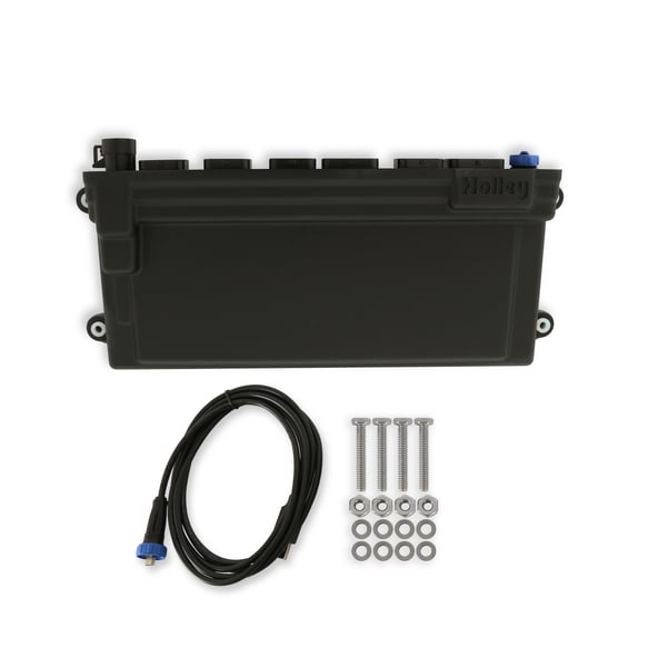
Holley EFI Dominator is a programmable US Holley engine-control unit; ECU part number 554-114 is listed by Holley. Holley ECU and harness parts guide · manufacturer comparison.
Identification and capabilities
The Dominator has six ECU connectors, two wideband channels, USB PC communication, internal/external logging and substantially expanded inputs and outputs. It can control supported drive-by-wire and automatic-transmission installations with the correct hardware, harness and software.
| Hardware | Manufacturer description |
|---|---|
| ECU identifier | 554-114 |
| Injector drivers | 12 injector drivers with high- and low-impedance support |
| Model-specific distinction | J1A/J1B are only the common main connectors. Additional Dominator connectors require the exact Dominator wiring and function allocation; never infer their pins from HP or Terminator. |
Injector impedance, timing hardware, firmware, sensor types and output allocation determine compatibility. Kits may use a model ECU with different vehicle-specific main and injector harnesses.
J1A and J1B ECU pinouts
Holley's ECU pinout gives J1A and J1B for HP, Dominator, Terminator X and X Max; this table records the Dominator interpretation. Source naming and ratings are preserved; verify connector orientation and model-specific harness, fuse and configuration before connection.
Connector J1A
| Position | Function |
|---|---|
| A1 | Coil negative input |
| A2 | Fuel pump output +12 V (10 A maximum) |
| A3 | Input 2 (capabilities depend on model) |
| A4 | Input 4 (capabilities depend on model) |
| A5 | TPS input |
| A6 | Points trigger output |
| A7 | Wideband 1 COMPR2 |
| A8 | Wideband 1 shield |
| A9 | Wideband heater negative |
| A10 | Switched +12 V input |
| A11 | Manifold air temperature input |
| A12 | Input 1 (capabilities depend on model) |
| A13 | Input 3 (capabilities depend on model) |
| A14 | Cam/crank ground |
| A15 | Gauge digital output |
| A16 | Wideband 1 COMPR1 |
| A17 | Wideband 1 VS−/IP+ |
| A18 | Sensor ground |
| A19 | Engine coolant temperature input |
| A20 | Oil pressure input |
| A21 | Knock 2 input |
| A22 | Cam sync input / ignition bypass output |
| A23 | MAP sensor input |
| A24 | CAN low |
| A25 | Wideband 1 VS+ |
| A26 | Sensor +5 V |
| A27 | Not used |
| A28 | EST/Spout output |
| A29 | Knock 1 input |
| A30 | Crank speed input |
| A31 | Fuel pressure input |
| A32 | CAN high |
| A33 | Wideband 1 IP+ |
| A34 | Wideband heater positive |
Connector J1B
| Position | Function |
|---|---|
| B1 | IAC A low |
| B2 | IAC A high |
| B3 | Output 4 (ground/PWM−) |
| B4 | Injector F |
| B5 | Injector G |
| B6 | Injector H |
| B7 | Injector E |
| B8 | IAC B low |
| B9 | IAC B high |
| B10 | Output 3 (ground/PWM−) |
| B11 | Output 2 (high-side / PWM+) |
| B12 | Output 1 (high-side / PWM+) |
| B13 | Injector D |
| B14 | EST ground output |
| B15 | EST 2 (cylinder 2) |
| B16 | EST 4 (cylinder 4) |
| B17 | EST 6 (cylinder 6) |
| B18 | EST 8 (cylinder 8) |
| B19 | Injector A |
| B20 | EST 12 V output |
| B21 | EST 1 (cylinder 1) |
| B22 | EST 3 (cylinder 3) |
| B23 | EST 5 (cylinder 5) |
| B24 | EST 7 (cylinder 7) |
| B25 | Injector C |
| B26 | Injector B |
Input type codes and B11/B12 drive polarity vary across the families; refer to Holley's auxiliary I/O harness guide. Additional connectors are not represented by this table.
Software and sources
- Holley EFI software and support
- Main connector pinout and manufacturer cautions
- ECU, engine and ignition harness selection
- Holley EFI family index
Source review: 17 November 2026.