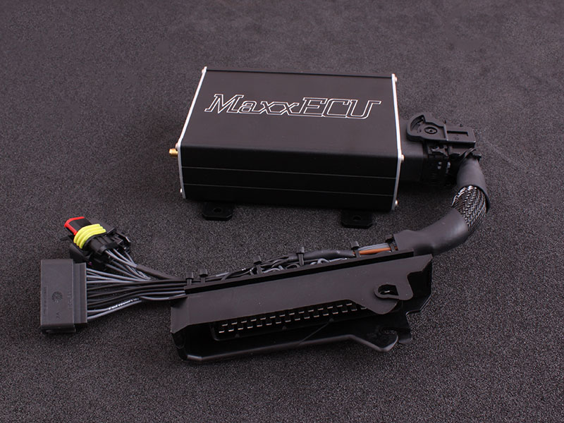
MaxxECU Audi S2/S4/S6 (AAN) plug-in adapter connects a compatible MaxxECU to an application-specific factory wiring loom. It is an adapter and installation package rather than a new universal ECU architecture. The published MaxxECU application guide identifies its intended configuration and connector details.
Identification and scope
Match the vehicle, engine, original ECU and connector, transmission, adapter revision and the MaxxECU unit to the guide. GEN1 adapters and earlier V1-specific adapters are not automatically interchangeable. The manufacturer's GEN1 adapter index separates the vehicle-specific instructions.
Manufacturer-listed examples
These examples and qualifications are transcribed from the manufacturer's adapter guide. A listed platform is not proof that every market or hardware combination is compatible; check the exact ECU, loom and transmission.
| Vehicle | Engine code | Year | LSU sensor | Note |
|---|---|---|---|---|
| Audi S2 | ABY | 1993 - 1996 | External sensor needed | |
| Audi S4 (C4) | AAN | 1991 - 1994 | External sensor needed | No support for the V8 engine, check your engine code |
| Audi S6 (C4) | AAN | 1995 - 1997 | External sensor needed | No support for the V8 engine, check your engine code |
| Audi RS2 | ADU | 1994 - 1996 | External sensor needed |
Vehicle and ECU functions
Manufacturer's mapping and availability for this particular adapter; a yes or no applies only to the configuration named in the table. Confirm adapter revision, hardware and calibration with the original guide.
| OEM options | MaxxECU IO | STREET | V1/RACE/PRO | Note |
|---|---|---|---|---|
| Fuel pump | GPO 1 | Yes | Yes | |
| Tachometer | GPO 8 | Yes | Yes | |
| Check engine light | GPO 3 | Yes | Yes | |
| Idle solenoid | INJ 6 | Yes | Yes | |
| Boost solenoid | GPO 2 | Yes | Yes | |
| Engine fan | Vehicle control | Yes | Yes | |
| Vehicle speed | DIN 2 | Yes | Yes | |
| AC | - | No | No | |
| AC request | - | No | No | |
| EVAP solenoid | - | No | No | Stock EVAP is not controlled |
| Bluetooth ( MDash) | - | No | Yes | |
| Knock sensor(s) | - | No | No | |
| EGT option | - | Yes, external | Yes, direct |
Additional connector
The following is the extra connector table in the model-specific guide. Refer to its illustrated connector and installation notes for view, cable colours, electrical limits and revision; these positions are not the factory ECU connector.
| Pin | Description | Usage | Note |
|---|---|---|---|
| 1 | Wide band (VREF) | ||
| 2 | Wide band (VS) | ||
| 3 | Wide band (shield) | ||
| 4 | Wide band (H-) | ||
| 5 | INJ 7 | Output | Not available on MaxxECU STREET |
| 6 | INJ 8 | Output | Not available on MaxxECU STREET |
| 7 | GPO 7 | Output or digital input | Not available on MaxxECU STREET |
| 8 | GPO 4 | Output | Not available on MaxxECU STREET |
| 9 | Wide band (IP) | ||
| 10 | Wide band (RCAL) | ||
| 11 | +12V | Output | |
| 12 | +12V | Output | |
| 13 | Engine GND | ||
| 14 | AIN 1 | temperature input | |
| 15 | AIN 2 | temperature input | |
| 16 | AIN 3 | 0-5V analog input |
Installation and verification
The adapter may require an external wideband sensor, a MAP hose, additional connectors, or other changes depending on the application and kit. Do not assume that every factory function, emissions device, dashboard feature, air-conditioning function or transmission is supported. Check the model-specific tables, base configuration and full manufacturer installation guide for the exact unit before connection and calibration.
Documents
- MaxxECU Audi S2/S4/S6 (AAN) adapter installation and pinout
- GEN1 plug-in compatibility and wiring index
- MaxxECU manufacturer and universal-model index
Sources reviewed 17 November 2026.