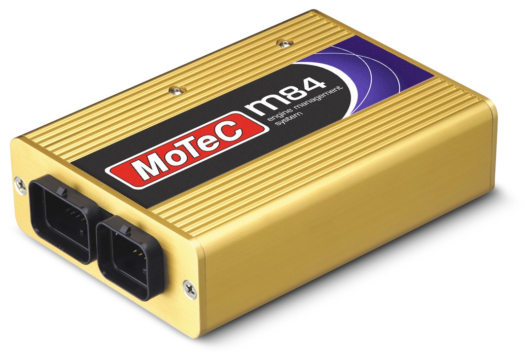
MoTeC M84, part 13084, is an earlier Gold Box engine controller listed in MoTeC's obsolete-product archive. M84 Gold Box family. Manufacturer Gold Box archive; manufacturer model glossary.
Identification and compatibility
Read the full ECU part number, connector, firmware, options and the label before identifying the correct model. Configurations and optional engine packages vary; a similar suffix, physical plug or a common calibration does not establish a universal pinout or exact cylinder capability. The manufacturer's archived product listing provides M84-specific documentation.
Pinout and software
Consult the MoTeC M84 product and wiring downloads and MoTeC legacy downloads. Model and marine-labelled variants must be checked against their own part numbers, connector drawings and firmware. Confirm connector orientation and the complete power, ground, sensor, injector and ignition circuits with the original documentation before wiring.
These units use a legacy ECU Manager or EMP software generation appropriate to the exact controller and firmware; M1 Tune is for M1 products. See MoTeC software archive and the MoTeC manufacturer guide.
Connector pinout
The MoTeC M84 datasheet #13084 revision 1.1 lists connector A (34 pin, mating plug #65044) and connector B (26 pin, mating plug #65045). Functions shown here use the source's example assignments; actual setup and available options may differ. Check connector orientation and electrical limits in the original.
Connector A — 34 positions
| Pin | Designation | Function in source |
|---|---|---|
| 1 | AUX2 | Auxiliary Output 2 |
| 2 | 5V-ENG | Sensor 5 V |
| 3 | IGN1 | Low Side Ignition 1 |
| 4 | IGN2 | Low Side Ignition 2 |
| 5 | IGN3 | Low Side Ignition 3 |
| 6 | IGN4 | Low Side Ignition 4 |
| 7 | IGN5 | Low Side Ignition 5 |
| 8 | IGN6 | Low Side Ignition 6 |
| 9 | 5V-AUX | Auxiliary 5 V |
| 10 | Ground | Battery Negative |
| 11 | Ground | Battery Negative |
| 12 | 8V-ENG | Sensor 8 V |
| 13 | 8V-AUX | Auxiliary and CAN 8 V |
| 14 | AV1 TP | Throttle Position Input |
| 15 | AV2 MAP | Manifold Pressure Input |
| 16 | AV3 MAF | Mass Air Flow Input |
| 17 | AV4 FP | Fuel Pressure Input |
| 18 | AUX1 | Auxiliary Output 1 |
| 19 | INJ1 | Injector 1 |
| 20 | INJ2 | Injector 2 |
| 21 | INJ3 | Injector 3 |
| 22 | INJ4 | Injector 4 |
| 23 | AUX3 | Auxiliary Output 3 |
| 24 | AUX4 | Auxiliary Output 4 |
| 25 | AV5 OP | Oil Pressure Input |
| 26 | V BAT | Battery Positive |
| 27 | INJ5 | Injector 5 |
| 28 | INJ6 | Injector 6 |
| 29 | INJ7 | Injector 7 |
| 30 | INJ8 | Injector 8 |
| 31 | AUX5 | Auxiliary Output 5 |
| 32 | AUX6 | Auxiliary Output 6 |
| 33 | AUX7 | Auxiliary Output 7 |
| 34 | AUX8 | Auxiliary Output 8 |
Connector B — 26 positions
| Pin | Designation | Function in source |
|---|---|---|
| 1 | REF | Crank Reference Input |
| 2 | SYNC | Cam Sync Timing Input |
| 3 | AT1 AT | Air Temp input |
| 4 | AT2 ET | Engine Temp input |
| 5 | AT3 User2 | User Analog Temp Input |
| 6 | AT4 SW | Switch Input 4 |
| 7 | AT5 SW | Switch Input 5 |
| 8 | DIG1 | Left Drive Speed |
| 9 | DIG2 | Right Drive Speed |
| 10 | DIG3 | Left Ground Speed |
| 11 | DIG4 | Right Ground Speed |
| 12 | LA2-S | Lambda 2 Sensor input |
| 13 | LA2-P | Lambda 2 Pump Current |
| 14 | 0V-Comms | Comms 0 V |
| 15 | 0V-AUX | Auxiliary 0 V |
| 16 | 0V-ENG | Sensor 0 V |
| 17 | TX-232 | RS232 Transmit Data |
| 18 | RX-232 | RS232 Receive Data |
| 19 | AT6 SW | Switch Input 6 |
| 20 | AV6 | Analog Voltage Input 6 |
| 21 | AV7 | Analog Voltage Input 7 |
| 22 | AV8 | Analog Voltage Input 8 |
| 23 | CAN_HI | CAN Comms High |
| 24 | CAN_LO | CAN Comms Low |
| 25 | LA1-S | Lambda 1 Sensor Input |
| 26 | LA1-P | Lambda 1 Pump Current |