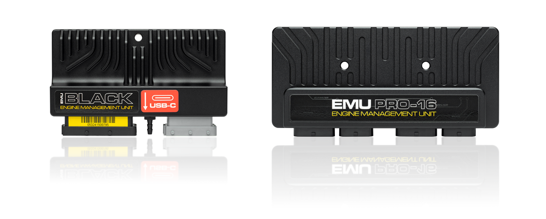
Pro-16 has the larger Pro input/output complement. The manufacturer lists 16 peak-and-hold injector outputs, up to twelve active or ten passive coils, 16 low-side auxiliary outputs, four full H-bridges, two LSU 4.9 controllers, two electronic throttle controllers, two CAN buses and LIN. Its IP65 case measures 197 × 95 × 38 mm. Direct-injection applications require the separate GDI Driver. Manufacturer product specification · Manufacturer comparison.
Connector pinout and wiring
The linked v1.1 document applies to board revision F or newer and serial 101-2242-xxxxx and higher. Connector housings A 4-1437290-1, B 1473416-1, C 4-1437290-0 and D 3-1437290-7 are AMP Superseal 1.0. Check the drawing and obtain the matching document for earlier hardware. CAN1 provides PC communication; USB pins connect a flash logging drive. Exact-model manufacturer pinout.
Software and installation
Record the ECU serial, firmware, software and project versions and confirm assigned outputs and trigger inputs before connecting loads. The manufacturer downloads contain current software, manuals and supported base maps. Base maps do not establish the correct pinout for a particular vehicle. Compare with the ECUMaster family guide.
Connector pin tables
The tables transcribe ECUMaster Pro-16 pinout v1.1, board revision F or later, serial 101-2242-xxxxx and higher. Use the numbered manufacturer connector drawings and mating-housing keys to establish orientation; these tables describe ECU connector positions, not sensor-side terminal numbers. Configurable and shared functions depend on software setup. Refer to the source for protection, currents, grounds, termination and sensor-wiring conditions before use.
Connector A
| Pin | Manufacturer function |
|---|---|
| A1 | Ignition 8 |
| A2 | Injector 1 |
| A3 | Injector 2 |
| A4 | Injector 3 |
| A5 | Injector 4 |
| A6 | Injector 5 |
| A7 | Injector 6 |
| A8 | Injector 7 |
| A9 | Injector 8 |
| A10 | Ignition 7 |
| A11 | Power ground |
| A12 | +5 V source A |
| A13 | Digital 2 |
| A14 | Digital 4 |
| A15 | Digital 8 |
| A16 | Digital 6 (turboshaft) |
| A17 | Power ground |
| A18 | Ignition 6 |
| A19 | Power ground |
| A20 | Digital ground |
| A21 | Digital 1 (crank) |
| A22 | Digital 3 |
| A23 | Digital 7 |
| A24 | Digital 5 (turboshaft) |
| A25 | Auxiliary 9 |
| A26 | Ignition 5 |
| A27 | Ignition 4 |
| A28 | Ignition 3 |
| A29 | Ignition 2 |
| A30 | Ignition 1 |
| A31 | CAN 1 high (PC) |
| A32 | CAN 1 low (PC) |
| A33 | CAN 2 high |
| A34 | CAN 2 low |
Connector B
| Pin | Manufacturer function |
|---|---|
| B1 | Auxiliary 1 (wideband heater option) |
| B2 | Auxiliary 2 (wideband heater option) |
| B3 | Auxiliary 3 (wideband heater option) |
| B4 | Auxiliary 4 (wideband heater option) |
| B5 | Auxiliary 5 |
| B6 | Auxiliary 6 |
| B7 | Auxiliary 7 |
| B8 | +12 V supply |
| B9 | Digital ground (flash drive) |
| B10 | USB D− (flash drive) |
| B11 | USB D+ (flash drive) |
| B12 | +5 V source A (flash drive) |
| B13 | Auxiliary 8 |
| B14 | +12 V supply |
| B15 | +12 V switched |
| B16 | Knock sensor 1 |
| B17 | Knock sensor 2 |
| B18 | Wideband 2 VGND (LSU 4.9) |
| B19 | Power ground |
| B20 | Wideband 1 Ip (LSU 4.9) |
| B21 | Wideband 1 Vs (LSU 4.9) |
| B22 | Wideband 1 Rcal (LSU 4.9) |
| B23 | Wideband 1 VGND (LSU 4.9) |
| B24 | Wideband 2 Ip (LSU 4.9) |
| B25 | Wideband 2 Vs (LSU 4.9) |
| B26 | Wideband 2 Rcal (LSU 4.9) |
Connector C
| Pin | Manufacturer function |
|---|---|
| C1 | Auxiliary 10 |
| C2 | Auxiliary 11 |
| C3 | Auxiliary 12 |
| C4 | Analogue 7 |
| C5 | Analogue 10 (2.2 kΩ pull) |
| C6 | H-bridge 1A |
| C7 | H-bridge 2B |
| C8 | H-bridge 3A |
| C9 | H-bridge 2A |
| C10 | Analogue 1 (MAP) |
| C11 | Analogue 3 |
| C12 | Analogue 5 |
| C13 | Analogue 8 |
| C14 | Analogue 11 (2.2 kΩ pull) |
| C15 | Analogue 13 (1 kΩ pull) |
| C16 | Analogue 15 (330 Ω pull) |
| C17 | H-bridge 3B |
| C18 | Analogue 2 |
| C19 | Analogue 4 |
| C20 | Analogue 6 |
| C21 | Analogue 9 (2.2 kΩ pull) |
| C22 | Analogue 12 (2.2 kΩ pull) |
| C23 | Analogue 14 (1 kΩ pull) |
| C24 | Analogue 16 (100 Ω pull) |
| C25 | H-bridge 1B |
| C26 | LIN |
| C27 | +5 V source B |
| C28 | +5 V source B |
| C29 | Analogue ground |
| C30 | Power ground |
| C31 | Precision analogue 1 |
| C32 | Precision analogue 2 |
| C33 | Precision analogue 3 |
| C34 | Precision analogue 4 |
Connector D
| Pin | Manufacturer function |
|---|---|
| D1 | Injector 10 |
| D2 | Injector 11 |
| D3 | Injector 12 |
| D4 | Injector 13 |
| D5 | Injector 14 |
| D6 | Injector 15 |
| D7 | Injector 16 |
| D8 | Injector 9 |
| D9 | Analogue 17 |
| D10 | Analogue 18 |
| D11 | Digital 9 / analogue 19 |
| D12 | Digital 10 / analogue 20 |
| D13 | Auxiliary 13 |
| D14 | H-bridge 4A / ignition 11 |
| D15 | Precision analogue 6 |
| D16 | Precision analogue 8 |
| D17 | Analogue ground |
| D18 | Power ground |
| D19 | Auxiliary 14 |
| D20 | H-bridge 4B / ignition 12 |
| D21 | Precision analogue 5 |
| D22 | Precision analogue 7 |
| D23 | Ignition 9 |
| D24 | Ignition 10 |
| D25 | Auxiliary 16 |
| D26 | Auxiliary 15 |
On this Pro-16 revision, D11/D12 share digital and analogue functions, and D14/D20 share H-bridge and active-coil ignition functions. See the linked documentation for limitations.
CAN1 carries PC communications and has no internal terminator in the cited document. B9–B12 are the flash-drive connections; they are not the tuning PC connection. All named power and sensor grounds have the specific wiring requirements described by the manufacturer.