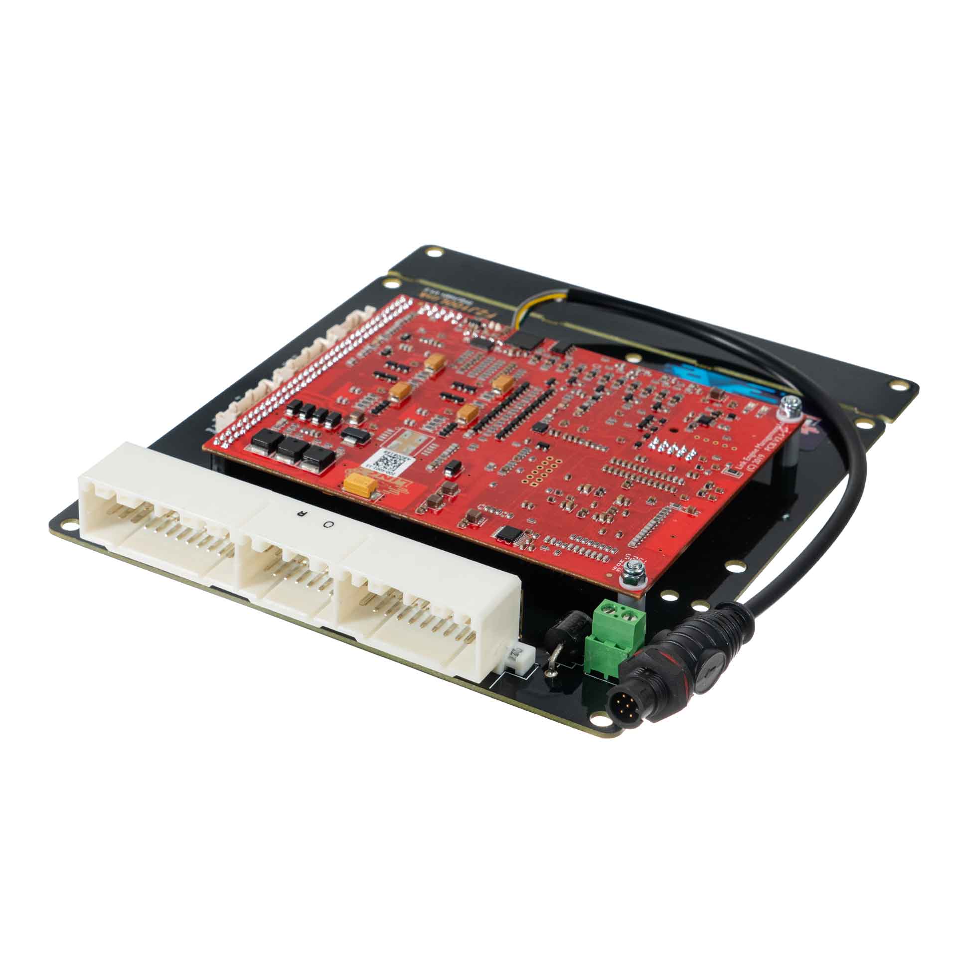
Link G4X FJ100X is a vehicle-specific programmable plug-in ECU for the Toyota Land Cruiser FZJ100 application listed in Link's model-specific manuals index. It is an application board rather than a universal wire-in ECU. Check the exact vehicle, market, engine, original ECU and board part number against the manufacturer's FJ100X installation manual.
Identification and installation
Record the Link model label and revision, donor factory ECU connector and car's engine and year. Plug-in boards connect to particular factory-harness layouts; the family or vehicle name alone does not establish every model-year or transmission combination. The manufacturer manual gives the supported application and any installation or configuration notes for this board.
G4X plug-in platforms offer configurable fuel and ignition control but available channels and features depend on the original header and board. The G4X plug-in general specifications are conditional on the particular application and do not mean every input is brought out to the factory harness.
Pinout and tuning
The FJ100X installation manual is the model-specific source for board pinouts, expansion connections, electrical cautions and startup configuration. Use its connector orientation and the exact board version; do not copy a wire-in ECU pinout onto a factory harness. PCLink and manual downloads; Link manufacturer overview.
Manufacturer connector schedules
From Link's FJ100X installation manual. Link describes the view as looking into the ECU from the wire side. A dash reproduces an unspecified source field; nc is Link's label. Confirm the vehicle and board revision before use. This guide covers the Land Cruiser FZJ100. Injector drives 7 and 8 are not exposed, according to Link.
Factory main header
| Factory pin | Link ECU channel | Factory function |
|---|---|---|
| 1 (B13) | Ground | — |
| 51 (C11) | DI 2 | — |
| 2 (B12) | Injector 1 | Injection |
| 52 (C10) | DI 8 | — |
| 3 (B11) | Injector 2 | Injection |
| 53 (C9) | DI 3 | — |
| 4 (B10) | Aux 1 | ISC Valve |
| 54 (C8) | DI 4 | — |
| 5 (B9) | DI 5 | Low Range Switch |
| 55 (C7) | DI 10 | — |
| 6 (B8) | Aux 2 | Tacho |
| 56 (C6) | nc | — |
| 7 (B7) | Ignition 1 | Ignition |
| 57 (C5) | Aux 12 | — |
| 8 (B6) | Aux 4 (3 Plug) / Ignition 2 (4 Plug) | Idle out / Ignition |
| 58 (C4) | Aux 13 | — |
| 9 (B5) | Trig 2 (3 Plug) / Ignition 3 (4 Plug) | Trig 2 / Ignition |
| 59 (C3) | nc | — |
| 10 (B4) | Trig 1 (3 Plug) / - (4 Plug) | Trig1 / - |
| 60 (C2) | DI 11 | — |
| 11 (B3) | nc | — |
| 61 (C1) | nc (+12V Constant) | — |
| 12 (B2) | Injector 5 | Injection |
| 62 (C22) | DI 7 | — |
| 13 (B1) | Aux 8 | Spare |
| 63 (C21) | Aux 11 | — |
| 14 (B26) | Ground | — |
| 64 (C20) | Aux 2 | — |
| 15 (B25) | Injector 3 | Injection |
| 65 (C19) | DI 9 | — |
| 16 (B24) | Injector 4 | Injection |
| 66 (C18) | An Volt 3 | — |
| 17 (B23) | nc | — |
| 67 (C17) | nc | — |
| 18 (B22) | Ignition 5 (Aux) | Spare |
| 68 (C16) | Aux 16 | - / Fuel Pump Speed Relay |
| 19 (B21) | Ignition 6 (Aux) | Spare |
| 69 (C15) | Aux 15 | — |
| 20 (B20) | Ignition 1 | Ignition |
| 70 (C14) | Aux 14 | — |
| 21 (B19) | Ignition 2 (3 Plug) / Trig 2 (4 Plug) | Ignition / Trig 2 |
| 71 (C13) | Aux 3 | — |
| 22 (B18) | Ignition 3 (3 Plug) / Trig 1 (4 Plug) | Ignition / Trig 1 |
| 72 (C12) | +14V | ECU Power Supply |
| 23 (B17) | Ground (NE-) | — |
| 24 (B16) | Ignition 4 (Aux) | Spare |
| 25 (B15) | Injector 6 | Injection |
| 26 (B14) | Ground | — |
| 31 (A8) | nc | — |
| 32 (A7) | An Volt 4 | AFM Signal |
| 33 (A6) | An Volt 5 | NB Oxy |
| 34 (A5) | Knock 1 | Knock |
| 35 (A4) | An Temp 3 | ECT |
| 36 (A3) | An Temp 4 | IAT |
| 37 (A2) | An Volt 6 | MAP |
| 38 (A1) | +5V Out | — |
| 39 (A16) | DI 6 | Transfer Neutral Switch |
| 40 (A15) | Aux 16 | Fuel Pump Speed Relay / - |
| 41 (A14) | An Temp 1 | Spare |
| 42 (A13) | Knock 2 | Knock |
| 43 (A12) | An Volt 1 | Spare |
| 44 (A11) | An Volt 2 | TPS (Main) |
| 45 (A10) | nc | — |
| 46 (A9) | Ground (Signal) | — |
Expansion connector
| Position | Link ECU channel | Function |
|---|---|---|
| Expansion 1 | Ground (Signal) | — |
| Expansion 2 | +5V Out | — |
| Expansion 3 | Aux 5 | — |
| Expansion 4 | Aux 6 | — |
| Expansion 5 | DI 1 | — |
| Expansion 6 | An Volt 8 | — |
| Expansion 7 | An Volt 7 | — |
| Expansion 8 | An Temp 2 | — |
| Expansion 9 | Aux 7 | — |
| Expansion 10 | Ignition 7 (Aux) | — |
| Expansion 11 | Ignition 8 (Aux) | — |
| Expansion 12 | +14V Output | — |
| Expansion 13 | An Volt 9 | — |
| Expansion 14 | An Volt 10 | — |
| Expansion 15 | An Volt 11 | — |
| Expansion 16 | An Volt 12 | — |
CAN 1/RS232 Connector
| Pin | Function | Wire colour |
|---|---|---|
| 1 | Comms GND | Brown |
| 2 | CAN1 L | Green |
| 3 | CAN1 H | White |
| 4 | RS232-RX | Grey |
| 5 | RS232-TX | Yellow |
CAN 2/OBD Connector
| Pin | Function | Wire colour |
|---|---|---|
| 1 | GND | Brown |
| 2 | CAN2 L | Green |
| 3 | CAN2 H | White |
| 4 | NC | Grey |
| 5 | +14V | Yellow |