Link G5 Voodoo Pro V2 is a later documented Voodoo Pro version. The V2 quick-start guide describes ECU headers A, B and E, plus separate Ethernet and four-way CAN 1 connectors.
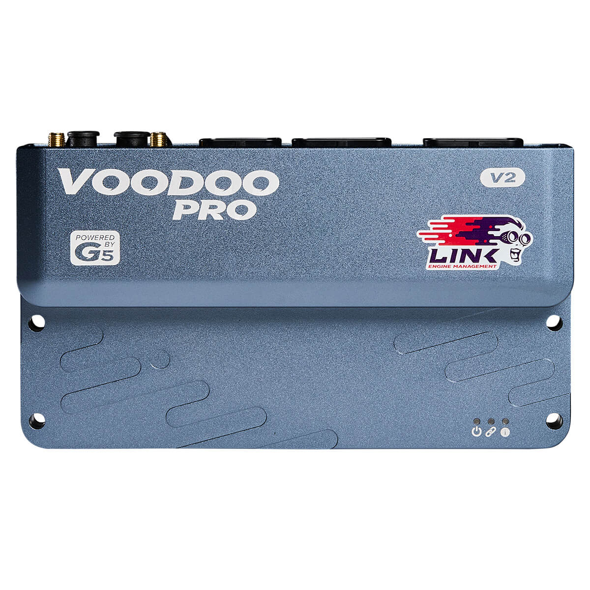
V2-specific power and communications
The V2 guide identifies A5 as the main ECU supply, A6 as the ignition-switch input and B5 as the H-bridge supply. CAN 1 is a four-way connector: pin 1 ground, 2 CAN low, 3 CAN high and 4 power. The guide specifies connector pin 1 relative to the locator notch, not mounted orientation. Link V2 guide.
Its eight ADIO pins support shared analogue, digital-input and auxiliary-output roles with different limits by function; the same pin cannot be allocated to separate simultaneous functions. The V2 has a different communications layout from V1: select the correct guide.
See Voodoo Pro overview for shared platform context. Identify revision and wiring before connecting power.