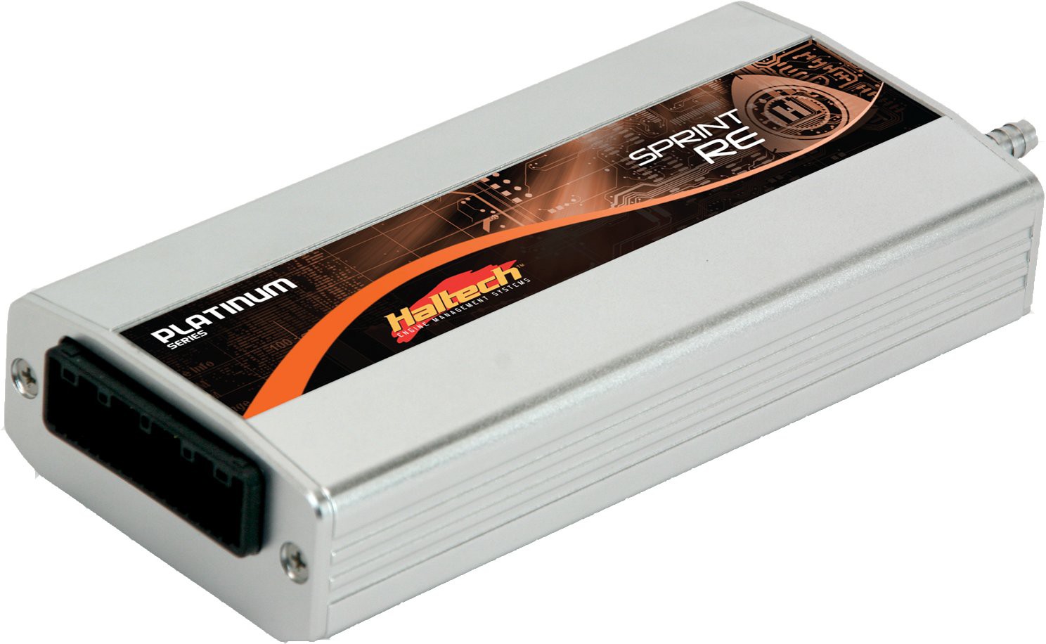
Haltech Platinum Sprint RE is a Platinum programmable engine-management model. Rotary-oriented Sprint ECU; Haltech's diagram labels four injection positions as primary and secondary injectors on rotor 1 and rotor 2, plus four ignition outputs. Its guide specifies high-impedance injectors or an appropriate ballast arrangement. Manufacturer specification or guide.
Identification and output allocation
Record the full ECU label, serial number, hardware or harness revision, software and existing calibration. These characteristics are model-specific; a superficially similar Platinum ECU should not be treated as a drop-in replacement. Counts can be limited by shared outputs, external modules and the engine's ignition and injection strategy.
Model-specific pinout and wiring
Consult the Platinum Sprint RE wiring documentation and the historic model manuals and connector archive where applicable. Select the named model and the precise harness revision; read its numbered connector view, driver characteristics, injector supply, power and ground notes. The connector appearance alone is not proof of identical pin functions.
Software and further information
ECU Manager for Platinum series. Haltech's download centre separates software and provides a legacy section. See Haltech standalone ECUs for the other families.
Manufacturer ECU connection table
These 32 positions are from page 28 of Haltech's Platinum Sprint RE quick-start guide. A dash is an unspecified position in that guide. Colour abbreviations use the first colour as the main insulation and the second as the stripe; L denotes blue.
| Pin | Harness colour | Connection |
|---|---|---|
| 1 | Y, 4-core grey | Trigger (+) |
| 2 | Y, 4-core grey/black | Home (+) |
| 3 | — | — |
| 4 | GY, shielded | Road speed input (DPI 1) |
| 5 | — | — |
| 6 | V/B | Tacho output (DPO 1) |
| 7 | V/BR | Thermofan output (DPO 2) |
| 8 | V/R | General purpose output 1 (DPO 3) |
| 9 | V/O | General purpose output 2 (DPO 4) |
| 10 | GY/R | +12 V switched |
| 11 | R | +12 V switched |
| 12 | B/Y | Fuel pump relay trigger |
| 13 | L/R | Injector 4 |
| 14 | L/BR | Injector 3 |
| 15 | L/B | Injector 2 |
| 16 | L | Injector 1 |
| 17 | G, 4-core grey | Trigger (−) |
| 18 | G, 4-core grey/black | Home (−) |
| 19 | — | — |
| 20 | O/B | Aux rev limiter (AVI 1) |
| 21 | GY/O, shielded | O2 sensor input |
| 22 | B/W | Signal ground |
| 23 | B | Power ground |
| 24 | V | Coolant temperature (ATI 1) |
| 25 | GY | Air temperature (ATI 2) |
| 26 | Y | MAP |
| 27 | W | TPS |
| 28 | O | +5 V |
| 29 | Y/G | Ignition output 4 |
| 30 | Y/O | Ignition output 3 |
| 31 | Y/R | Ignition output 2 |
| 32 | Y/B | Ignition output 1 |
The ignition outputs require suitable external ignition amplifiers or a CDI, as described in the guide. Configure functions for the actual installation and check current ratings in the manufacturer documentation.