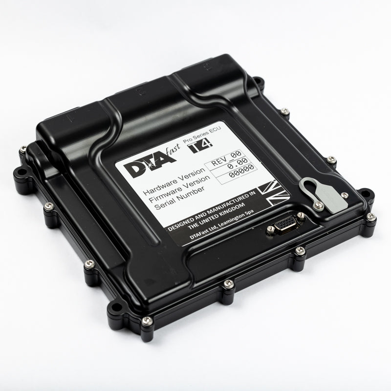
Product photograph: DTAFast. Used with permission.
DTAFast supplies programmable engine management systems. ECU product range and photographs; manufacturer wiring archive.
Individual ECU pages
- T series: T2i ignition only, T2, T4, T4+, T8, T8+, T12 and T12+.
- S series: S40 Pro, S60 Pro, S80 Pro, S100 Pro. S40 ignition-only is separately identified. Non-Pro labels are noted in the manufacturer-family comparison; the Pro pages describe Pro units.
- Historic: E4, E6, E8, E48 / E48EXP E48EXP ignition-only, and P8 Pro.
Models
- T series: T2, T2i, T4, T4+, T8, T8+, T12 and T12+.
- S series: S40, S60, S80 and S100.
- Earlier models in the archive: P8, E4, E6, E8 and E48.
The archive also contains an STC diagram; it is listed separately here because it is not established as a standalone engine ECU. Check the exact model and revision for availability and functions.
Model-by-model guide: T series
DTAFast's T range uses its T-Series PC application, configurable inputs and outputs, integrated Bosch wideband control and on-board data logging. Marketing descriptions are not interchangeable specifications: check the exact ECU, firmware and its individual diagram. A sample rate for one model does not establish that for all. DTA's product descriptions state that the PC software includes an oscilloscope for crank/cam diagnosis and firmware updating. DTAFast ECU range.
| Model | Documented operating scope and distinguishing features | Wiring |
|---|---|---|
| T2i | Ignition-only unit for carburetted engines; distributor ignition up to 12 cylinders or wasted spark up to four. Wideband measurement, flat shift, launch and fuel-pump relay control are described; it does not provide EFI control. | Product · Diagram |
| T2 | Four-cylinder wasted-spark and semi-sequential fuel injection; wideband closed-loop, launch, flat shift and VTEC. The supplier says it does not provide variable camshaft or traction control. | Product · Diagram |
| T4 | Up to four cylinders fully sequential; six or eight in semi-sequential mode. Single variable-cam control and traction control are listed. | Product · Diagram |
| T4+ | Four-cylinder fully sequential, six or eight semi-sequential; one drive-by-wire throttle, one knock input and one variable cam control. | Product · Diagram |
| T8 | Up to eight cylinders fully sequential or 12 semi-sequential; dual wideband lambda and two variable cam controls. | Product · Diagram |
| T8+ | Up to eight fully sequential or 12 semi-sequential; dual drive-by-wire, dual wideband, dual variable cam control, knock and paddle shift. | Product · Diagram |
| T12 | Up to 12 cylinders fully sequential with four variable cam controls and paddle shift support. | Product · Diagram |
| T12+ | Up to 12 cylinders fully sequential; dual drive-by-wire, dual knock sensing, four variable cam controls and paddle shift support. | Product · Diagram |
Earlier S series and Pro variants
There are S40/S60/S80/S100 and S40 Pro/S60 Pro/S80 Pro/S100 Pro designations in the ECUMaster S-series integration note; the 2019 DTAFast S-series manual covers the Pro range. The supplier's historical S-series feature matrix lists the following driver counts: they are output channels, not a promise of one independently controlled cylinder per output in every installation.
| Family | Historical feature matrix | Diagram |
|---|---|---|
| S40 Pro / ignition-only S40 variant | Two coil and two injector drivers; no cam input on that matrix. Ignition-only S40 also sold; verify its label and loom. | S40 |
| S60 Pro | Four coil and four injector drivers, cam input and one cam control. DTA's S60 Pro sheet describes four-cylinder sequential use or up to eight cylinders in non-sequential/wasted-spark operation. | S60 · S60 Pro sheet |
| S80 Pro | Eight coil and eight injector drivers; two cam inputs in the matrix. The S-series manual describes traction-control functions on S80 Pro and above. | S80 |
| S100 Pro | Ten coil and ten injector drivers in the historical matrix, with two cam inputs. Use its diagram and calibration rather than S80 assumptions. | S100 |
Pro firmware and non-Pro labels cannot be assumed equivalent. DTAFast's wiring archive also records P8, E4, E6, E8 and E48, including separate power and sensor sheets for E4/E6/E8. P8 and E48 require attention to crank-sensor rules and jumpers. Historical output and support coverage is incomplete. The separate STC unit is listed in DTA's archive as a distinct device and is not counted as a standalone ECU here.
T2 34-way connector — diagram version 1.03
This is the pin-insertion side of the T2 harness connector, not T2i or T4. The functions below follow DTAFast's six-page T2 diagram; configurable I/O assignments and hardware revision notes are in that document. Separate fused permanent and ignition feeds are shown.
| Pin | Function | Pin | Function |
|---|---|---|---|
| 1 | PWM 1 | 18 | PWM 3 |
| 2 | Lambda Nernst voltage | 19 | Crank |
| 3 | Coil 1 | 20 | Analogue 1 |
| 4 | Lambda VGND | 21 | Permanent 12 V |
| 5 | Lambda pump current | 22 | Analogue 2 |
| 6 | Coil 2 | 23 | Analogue 3 |
| 7 | Lambda trim resistor | 24 | Thermistor 1 |
| 8 | Injector 1 | 25 | Analogue 4 |
| 9 | Injector 2 | 26 | PWM 4 |
| 10 | PWM 2 | 27 | 5 V out |
| 11 | Digital 1 | 28 | Sensor ground |
| 12 | Wheel 1 | 29 | Sensor ground |
| 13 | Power ground 1 | 30 | Digital 2 |
| 14 | Power ground 2 | 31 | Ignition 12 V input |
| 15 | Lambda heater negative | 32 | Thermistor 2 |
| 16 | CAN high | 33 | Analogue 5 |
| 17 | CAN low | 34 | Analogue 6 |
T4 connector pinouts — version 1.04
Manufacturer diagram specifies pin-insertion side. The tables below include labelled positions; unlisted positions are shown as a dash in the source and should not be assigned. T4 is not T4+. DTAFast T4 wiring diagram v1.04
Connector 1
| Pin | Function |
|---|---|
| 1 | Coil 3 |
| 3 | PWM 3 |
| 4 | PWM 2 |
| 5 | PWM 1 |
| 9 | Injector 1 |
| 10 | Coil 1 |
| 13 | Power ground 1 |
| 14 | Power ground 2 |
| 17 | Injector 2 |
| 18 | Coil 2 |
| 25 | Injector 4 |
| 26 | Coil 4 |
| 31 | Ignition 12 V in |
| 34 | Injector 3 |
Connector 2
| Pin | Function |
|---|---|
| 1 | Analogue 2 |
| 2 | Wheel 1 |
| 3 | Analogue 10 |
| 4 | Digital 1 |
| 5 | Analogue 3 |
| 6 | Analogue 4 |
| 7 | Thermistor 1 |
| 9 | 5 V output |
| 10 | Analogue 1 |
| 12 | Crank sensor |
| 14 | Digital 4 |
| 15 | Digital 5 |
| 16 | Analogue 11 |
| 17 | Thermistor 3 |
| 19 | Analogue 6 |
| 21 | Sensor ground |
| 22 | Cam 1 |
| 24 | 5 V output |
| 25 | Thermistor 2 |
| 26 | CAN high |
| 28 | CAN low |
| 33 | Sensor ground |
| 34 | Analogue 9 |
Connector 3
| Pin | Function |
|---|---|
| 7 | Lambda 1 pump current |
| 8 | Lambda 1 VGND |
| 9 | Lambda 1 heater negative |
| 10 | PWM 8 |
| 11 | Lambda 1 trim resistor |
| 12 | Lambda 1 Nernst voltage |
| 17 | Analogue 7 |
| 18 | Analogue 8 |
| 22–25 | PWM 4–7 respectively |
| 26–27 | Permanent 12 V |
In this diagram the permanent 12 V supply must be fused. Hardware revision affects pull-ups; see the original wiring instructions.
Confirm the exact ECU, hardware revision and connector orientation before wiring. Configurable functions and electrical limits are model-dependent; consult the linked original diagrams.