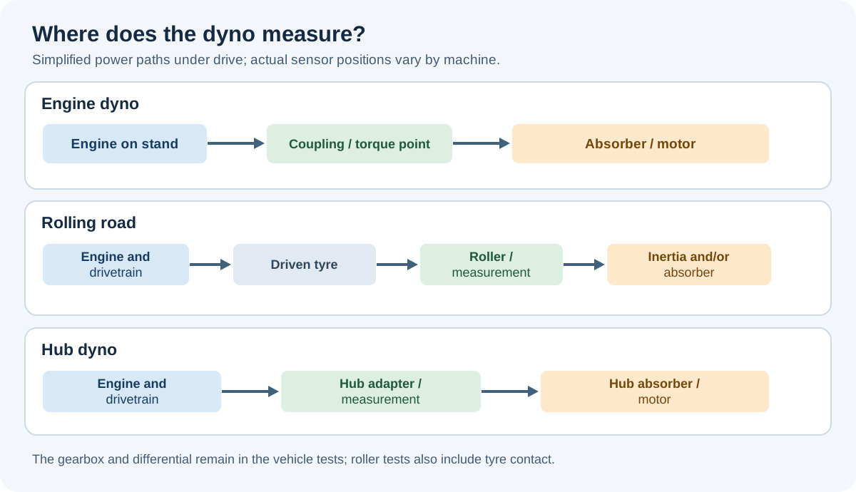
A dynamometer, often shortened to dyno, is equipment used to measure torque and rotational speed, or to infer power from a known accelerating inertia. In automotive work it can test an engine on a stand, a vehicle on rollers, or a vehicle coupled at its wheel hubs. A controllable power absorber can also impose load, allowing the operator to investigate operating points that a simple acceleration-only test cannot hold.
This section explains the machinery, measurement and control behind the figures. The installation, absorber, measuring system and controller are separate choices: for example, an eddy-current brake can be fitted to an engine, rolling-road or hub installation. See all Dynamometers articles.
Torque, speed and power
Torque is a turning moment, measured here in newton metres (N·m). Rotational speed is measured in revolutions per minute (rpm). At the same shaft and instant, mechanical power is P = T × ω, where T is torque in N·m and ω is angular speed in radians per second. Equivalently, power (kW) = torque (N·m) × rpm ÷ 9,549.3. Torque alone is not power: the speed at which it is produced matters. A brake's reaction force can be measured with a load cell at a known lever arm, or a shaft torque transducer can be used. For transient tests, torque and speed need to be time-aligned; 40 CFR 1065.15 describes synchronous speed and brake-torque measurement for engine work.
An inertia dyno instead uses the acceleration of a rotating mass whose moment of inertia is known. The simple relationship is net torque = inertia × angular acceleration. Losses and the inertia of coupled parts must be dealt with according to the measurement system; it is not a direct steady-state torque measurement.
Where the measurement is made
| Installation | Connection and normal measurement boundary | Typical use |
|---|---|---|
| Engine dyno | Engine output shaft coupled to a test-cell absorber; gearbox and driven wheels normally excluded. | Engine development, calibration and controlled durability tests. |
| Rolling road or chassis dyno | Driven tyres turn rollers; the transmission, final drive and tyre/roller interface are in the power path. | Whole-vehicle tuning, diagnosis, emissions or road-load simulation. |
| Hub dyno | Driven wheels are removed and absorbers attach at the hubs; the gearbox and final drive remain in the power path. | Vehicle testing without the driven tyre-to-roller contact. |
| On-road or on-car system | Depending on the product, this may mean a portable vehicle-attached dyno or a road-performance instrument estimating power from vehicle motion and assumptions. | Mobile testing and comparison; identify exactly what the equipment measures. |
These boundaries matter. Wheel or hub output cannot automatically be called crankshaft output. Transmission losses vary with operating conditions, and any calculated crank figure depends on its loss model and test procedure. Different dynos, tyre conditions, gearing, temperatures and correction standards can give different numbers; a repeatable before-and-after comparison needs the method and conditions recorded.
How load is produced
- Inertia: the engine accelerates a calibrated rotating mass. Acceleration rate is determined by net torque and inertia, rather than independently commanded by a brake.
- Eddy current: an electrically excited magnetic field induces currents in a moving conductor; their reaction resists motion and the absorbed energy becomes heat.
- Water brake: a rotor transfers momentum to water in a housing. Fluid movement and turbulence turn shaft work into heat, which the water removes.
- Oil-hydraulic: a pump drives oil against a controlled pressure difference. Oil flow, pressure control and cooling determine the operating envelope.
- Electric machine: a controlled motor/generator can absorb power electrically; an appropriately equipped system can also drive the test shaft. Energy may be dissipated or returned to the electrical supply, depending on the installation.
- Mechanical friction: historical friction brakes use a rubbing element and measure reaction force. Heat and wear limit continuous use.
The absorber's torque, speed, cooling and continuous-duty limits all matter. Maximum power at one speed does not mean the same maximum torque is available throughout the speed range. A passive absorber cannot drive the test shaft or hold substantial power indefinitely at zero speed.
What a test can show
An acceleration sweep records output as speed rises; acceleration rate, rotating inertia, filtering and heat conditions influence the result. A steady-state test uses a suitable load absorber and controller to hold an operating point while the operator examines torque, fuelling or other measurements. A road-load simulation applies a speed-dependent load to approximate driving resistance, sometimes with simulated inertia. The US EPA describes how coastdown-derived road load is apportioned between vehicle losses and dynamometer settings in its road-load analysis.
Preparation is part of the measurement: inspect the vehicle and test equipment, use the manufacturer's restraint and cooling arrangements, extract exhaust, and monitor temperatures and operating limits. Record the gear, tyre and restraint conditions where applicable, correction method, environmental readings, test mode and calibration. An appropriate vehicle test mode and compatible axle configuration are particularly important for modern four-wheel-drive and stability systems.
Further reading
- Mustang Dynamometer MD-600 manual — a real chassis dyno installation, load measurement and operating guidance.
- US engine-test work determination — synchronised torque and speed.
- EPA: isolating road-load losses — coastdown and chassis-dyno load setting.
- Magicmotorsport DynoRoad — an existing wiki page about one portable road-performance instrument.