An electric motor and regenerative hub dynamometer couples controlled electrical machines to a vehicle's driven hubs. Depending on its drive electronics and configuration, the system can absorb power from the vehicle, drive the vehicle's hubs, or do both. A regenerative installation can return some absorbed energy to the facility supply or reuse it within the test system.
These systems are used for performance, road-load, hybrid and electric-vehicle development. The gearbox and final drive remain in the measurement path; hub measurements do not include tyre-to-roller contact and are not direct engine-crankshaft measurements. Wheel removal and adapter arrangements depend on the installation. See Hub dynamometers.
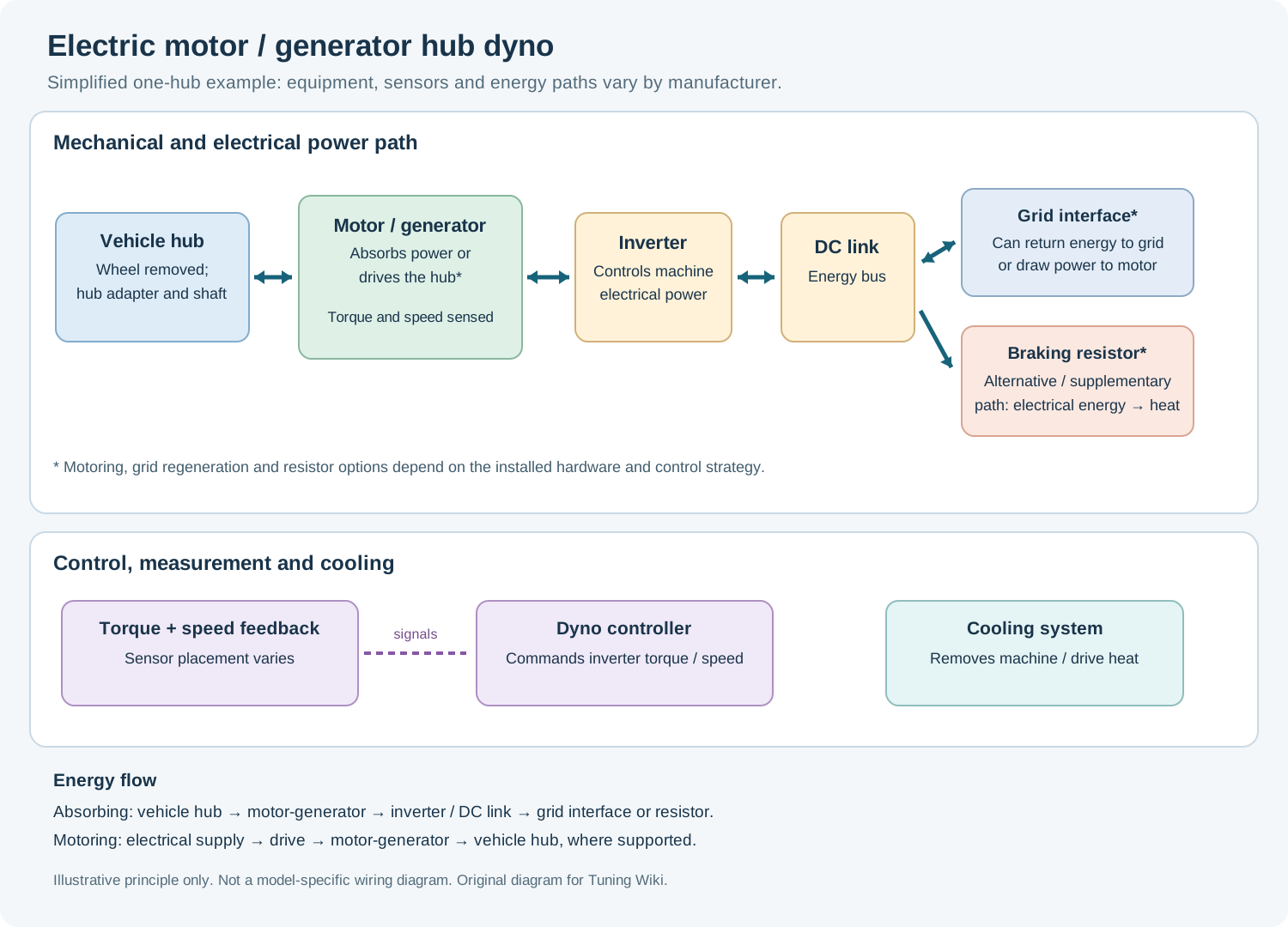
How the system works
- Hub connection: suitable adapters couple the vehicle's hubs to electrical machines. Depending on the design, the machine may drive the hub directly or through gearing and couplings.
- Machine and inverter: an electric machine develops controllable torque. Its power converter regulates the current and magnetic fields so that the machine can oppose hub rotation, or apply torque to drive it when the installation supports motoring.
- Feedback and control: speed sensors and torque transducers or calibrated reaction measurements feed the controller. Software compares the measurements with a chosen torque, speed or simulated-road target and commands the drive.
- Energy handling: in absorption, mechanical shaft power enters the machine and is converted to electrical energy, less losses. Depending on the equipment, energy may be returned through a regenerative supply converter, shared with another drive on a common electrical link, or dissipated in a suitable resistor or load bank. These are different configuration choices, not features guaranteed on every unit.
- Cooling and protection: electrical machines, drives and any resistors still generate heat. Their cooling, protection, supply connection and emergency systems must match the installation.
This is a simplified example: machine type, gearing, converters, sensors and where energy is sent vary. The Parker test-stand application note explains electric dynamometer drives and four-quadrant operation; Sierra CP describes test systems using regenerative energy sharing and battery emulation.
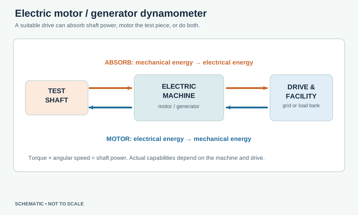
Absorption, motoring and four quadrants
Absorbing: the vehicle drives the hubs and the dyno applies opposing torque. Mechanical power flows into the dyno; a regenerative system can transfer part of that power back to the supply or another consumer. Conversion and auxiliary losses mean recovered power is less than shaft input.
Motoring: the dyno supplies torque to the hub. This can simulate overrun, downhill forces or other road loads, drive a powertrain for friction measurements, and support controlled electric-vehicle regenerative-braking tests. Actual capabilities depend on the machine, drive, software and vehicle.
Four-quadrant means both motoring and absorption in either shaft direction, within the equipment's torque–speed and thermal limits. With torque defined as the torque applied by the dyno to the hub, the sign combinations are:
| Hub speed | Dyno torque | Dyno mode |
|---|---|---|
| Positive | Positive | Motoring: power into the hub |
| Positive | Negative | Absorbing: power from the hub |
| Negative | Negative | Motoring: power into the hub |
| Negative | Positive | Absorbing: power from the hub |
Another report may use the opposite torque sign convention. At zero speed a suitably rated electric machine can hold torque, but instantaneous shaft power is zero. Standstill torque and duration still require adequate current, cooling and hardware ratings.
Two different meanings of regeneration
Dyno regeneration: when the vehicle drives an absorbing dyno, the dyno's generator and regenerative converter may return part of the absorbed energy to the building supply or share it with other electrical loads.
Vehicle regenerative braking: during a suitably configured test, the dyno can motor the hubs while the vehicle's own electric drive resists rotation and sends energy toward its battery or electrical system. The dyno is then supplying mechanical power rather than absorbing it. Whether the vehicle actually charges depends on its controls, battery state and test conditions. The two energy paths can be investigated on the same installation at different points in a test.
Torque, speed and reported power
A hub-mounted system can use a front-end shaft torque transducer and speed sensor; other installations use a calibrated reaction arm and load cell. For each measured shaft and instant, power (kW) = torque (N·m) × speed (rpm) ÷ 9,549.3. Calculate each hub's signed power using its own speed and torque, then add the simultaneous powers as appropriate. A torque reading at the hub must not be multiplied directly by engine rpm.
Electrical power at the converter, mechanical power at the dyno shaft and electrical power at the vehicle battery are different measurement points. Motor, gearbox, inverter and auxiliary losses separate them. During transients, shaft inertia, sensor alignment, sample timing and the equipment's compensation method affect reported output. Record measurement point, direction, gear, calibration, test mode and correction standard. See measurement and interpreting results.
Road simulation and multiple hubs
A real-time controller can command torque or speed and, where supported, use a vehicle model to simulate aerodynamic drag, rolling resistance, gradient and vehicle inertia. The physical dyno and vehicle still have rotating inertia; simulated inertia and dynamic compensation depend on the equipment and tuning. Not every hub system supports every manoeuvre, steering, independent wheel control or a particular vehicle-in-the-loop interface.
On suitable multi-machine installations, each hub can be controlled separately or coordinated with the others. This supports tests of torque distribution, different axle speeds and simulated manoeuvres, but unintended speed differences can affect a vehicle's differential, clutch or traction systems. Use the setup approved for the vehicle and test equipment. See ROTOTEST Energy 4WD documentation and Sierra CP powertrain systems.
Manufacturers and models
These examples identify electric hub-coupled products and configurable development systems; they are not a complete market list. Four-quadrant operation, supply regeneration, control channels and options must be confirmed for the exact installation. The manufacturer photographs below are used with permission.
ROTOTEST Energy
ROTOTEST Energy is a four-quadrant electric hub-dyno family with front-end torque transducers and speed sensors. Its manufacturer description names DynoVision operating software and Datmon measurement software. The Energy 4WD datasheet specifies road-load and constant-speed modules, a high-dynamic controller and distinct continuous and momentary limits. Energy 500-250 4WD is a documented configuration; climate-protected and NVH variants are also offered. Check exact ratings and regeneration hardware for the model and generation.
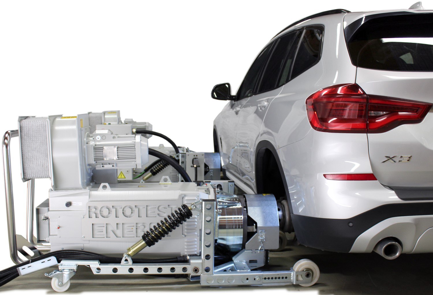
Earlier ROTOTEST VPA-RX units used hydraulic loading, rather than the Energy electric machines; see hydraulic hub dynos.
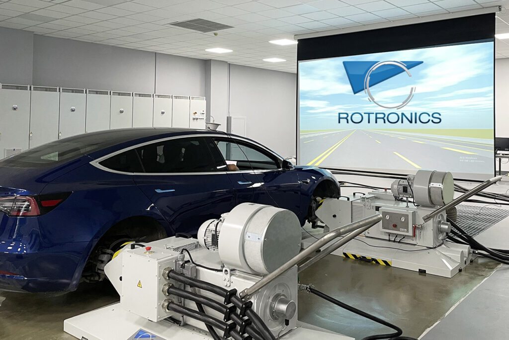
Rotronics Hubscan AC
Rotronics describes Hubscan AC as a four-quadrant electric hub test system capable of braking and motoring. Its published series includes Hubscan 120, 280, 400, 600, 1100 and 2000; the source specifies ratings per axle and distinguishes rated values from intermittent S6-20% values. The named AC system should not be confused with Rotronics' eddy-current Hubscan versions. Some configurations support independent wheel control and simulation interfaces; check the supplied options.
Mustang Advanced Engineering axle-hub dynamometers
Mustang Advanced Engineering describes AC axle-hub dynamometers with torque-flange measurement and 2WD, 4WD, 6WD or 8WD configurations. Its drive-package options include fully regenerative systems that can return absorbed power to the grid. They are configurable test systems: confirm the motor, drive, recovery and control capabilities of the particular quotation. The manufacturer page was unavailable when checked; current availability has not been verified.
Sierra CP road-speed hub systems
Sierra CP Engineering describes road-speed output machines for full vehicles or powertrain rigs, hub mounting hardware, regenerative inverter-drive suites and independently controlled outputs. Its EV test systems can use multi-drive energy sharing and CADET automation. These are engineered configurations rather than a single fixed hub-dyno model; verify the selected hub interface, machines, energy routing and controller.
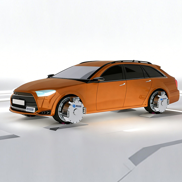
JINGKETEST WHD
JINGKETEST describes its WHD wheel-hub dynamometer system as a two- or four-unit vehicle test system with four-quadrant loading, steering-related simulation and internal energy reuse, with surplus grid feedback. Verify facility compatibility, vehicle mounting and the exact energy-recovery and control options with the supplier.
Specifying and operating a system
Ask for hub torque–speed curves in each relevant direction, rated and peak power with their durations, allowable inertia and axle load, control response, shaft measurement location and calibration. Establish whether the drive can motor and regenerate, where energy goes, and the permitted grid or load-bank capacity. Cooling demand remains even in a regenerative system. Electrical power quality, protection, isolation and facility approval are installation-specific.
Use the manufacturer's prescribed wheel adapters, fasteners, supports, guarding, vehicle restraints and interlocks, plus suitable vehicle and dyno cooling and exhaust extraction when required. Electric vehicle high-voltage systems and a powered hub machine need the facility's trained personnel and isolation procedures. See test setup and safety.
Comparison with other hub dynos
An eddy-current hub dyno dissipates absorbed shaft power mainly as heat and cannot itself motor the hub. A hydraulic hub dyno uses a pump and controlled fluid load. An electric motor/generator system can be built to absorb and motor, with optional energy recovery, but its capabilities depend on the particular machine and installation.
Related: Dynamometers · Hub dynamometers · Electric motor and generator dynamometers · Control systems.
Compare the options: Compare hydraulic, eddy-current and electric hub dynamometers.