Fluid dynamometers use a liquid to transfer and dissipate mechanical power. Two arrangements deserve separate names: the water brake exchanges momentum between a rotor, water and stator; a hydrostatic oil dynamometer normally drives a hydraulic pump against controlled pressure. Both apply load, but they do not work by the same mechanism. See Dynamometers.
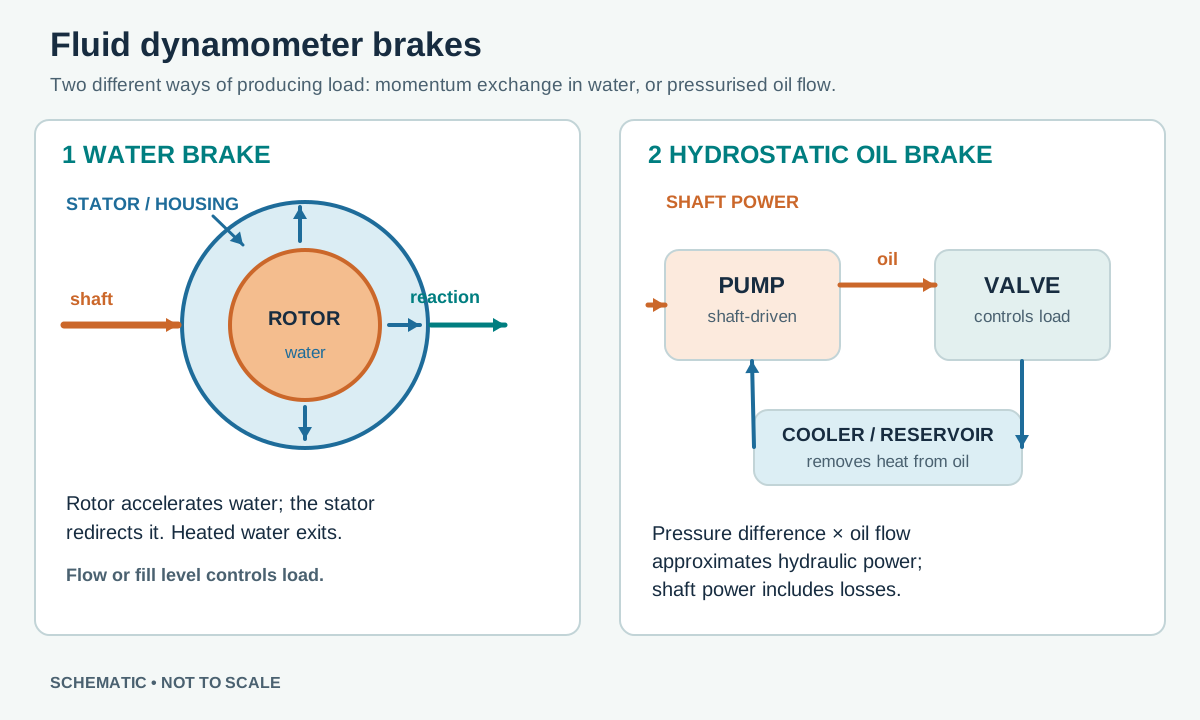
Water brake principle
An engine or transmission turns one or more vaned rotors inside a housing with stator pockets. Water admitted into the working space is accelerated by the rotor and redirected by the stator. The exchange of momentum resists rotation; turbulence and fluid friction convert the work into heat. The reaction tries to rotate the housing, which is restrained by a torque arm and load cell. Force times the perpendicular arm length gives reaction torque; multiplying torque by angular speed gives mechanical power at that point.
In Power Test's X-Series example, a supply valve or servo-operated inlet manifold controls water admitted to regulate load. Other designs use different control arrangements, so valve function depends on the machine. Water is circulated out to carry heat away and is replaced or cooled in a suitable circuit. Water supply and temperature are essential operating limits. Power Test X-Series engine dynamometers brochure; CNR STEMS: Hydraulic Dynamometer.
Hydrostatic oil brake
For hub-mounted examples and their measurement systems, see Hydraulic hub dynamometers.
The test shaft drives a positive-displacement hydraulic pump. The pump moves oil against pressure set by a valve, pump displacement control or another hydraulic load. Increasing pressure difference or effective displacement increases the shaft torque required within the operating range. Throttling converts hydraulic energy to heat; oil is filtered and cooled before returning to the reservoir. A relief valve limits pressure but must be correctly designed and rated as part of the whole circuit.
Hydraulic fluid power is approximately pressure difference multiplied by actual flow, P = Δp × Q in consistent SI units. This is not necessarily shaft power: pump efficiency, leakage, mechanical losses and any measurement locations matter. A calibrated shaft-torque transducer and speed measurement can provide direct mechanical power. A University of Minnesota hydrostatic dyno study describes both an absorbing pump-and-valve arrangement and a specialised system with a separate hydraulic supply and accumulator capable of motoring. An oil brake should not be assumed to have motoring capability merely because it uses a pump. University of Minnesota, Design and Construction of a Hydrostatic Dynamometer.
Practical differences and limits
- Water brakes can absorb substantial power with suitable water supply and cooling, but torque capacity changes with speed and water level; check the actual torque–speed map and do not assume a useful static holding torque.
- Oil systems need correctly rated lines, valves, cooling, filtration and pressure relief. Temperature, viscosity, leakage and cavitation can affect performance and measurement.
- Rated peak power is not necessarily continuous power. Cooling and operating duration can set a lower sustained limit. At zero speed, mechanical power is zero even when a system can produce static torque.
- Manual valves can apply load; servo valves and feedback controllers can automate a speed or torque target. See Dynamometer Control Systems.
Water used only to cool an eddy-current brake does not make that brake a water-brake absorber. Follow the equipment manufacturer's cooling, guarding and shutdown instructions.
Manufacturer example
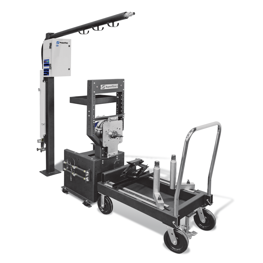
Example manufacturer: SuperFlow SF-902S is a water-brake engine dynamometer with a test stand and controls. Its water and power requirements are specific to the installation; consult the manufacturer.
Control methods: inlet, outlet and pump load
Water-brake response depends on water supplied, water level or pressure in the working cavity, speed and the design of the rotor and stator. Some machines control an inlet valve; others meter the outlet, and some installations control both. Power Test's X-Series brochure describes an optional servo-controlled inlet manifold, while the SuperFlow SF-902S describes outlet-valve control. Do not transfer a valve position or controller tuning from one system to another without the correct manual.
In a pump-based hydraulic circuit, a restriction or controlled pump changes pressure difference and hence shaft resistance. Oil must have a suitable return, cooling, filtration and properly engineered pressure-limiting path. A load cell, an in-line shaft transducer or a calibrated hydraulic model may be used depending on design. A ROTOTEST patent application illustrates one pump-based hub loading arrangement with measured reaction; it is not a universal schematic for all commercial units.
Heat, water supply and continuous testing
A fluid absorber must reject the energy taken from the shaft. For illustration only, if 100 kW is transferred entirely into a steady water flow of 1 kg/s, and the water's specific heat is approximated as 4.18 kJ/(kg·°C), the ideal temperature rise is about 24 °C. Real installations also have other losses, changing conditions and manufacturer-specified inlet temperature, flow, discharge and pressure requirements. This example does not size a test cell; use the actual equipment specification. A closed recirculating system still needs a heat exchanger or other means to remove the accumulated energy.
Water quality, stable supply pressure, flow monitoring, temperature and proper drainage matter for water brakes. A separate cooling-water circuit may cool hydraulic oil or an eddy-current brake; in those cases water removes heat but is not necessarily the fluid producing braking torque. Power Test discusses water supply pressure and load stability. For oil systems, check fluid condition, filters, hose ratings, leaks, viscosity and cooling according to the equipment maker.
Examples of fluid absorber families
- SuperFlow SF-902S is an engine water-brake system with outlet servo control. Its product page identifies the controller and speed pickup; particular ratings and options belong to that model.
- Power Test X-Series includes the 35X, 45X and 50X water-brake families for differing torque, speed and power envelopes; its brochure shows model-specific curves and inlet arrangements.
- Froude F-series water-brake models use rotor/stator fluid loading. The F-series information distinguishes individual models and ratings.
- Dynapack DAQ systems are a different fluid arrangement: a hub drives a hydraulic pump. See the manufacturer's model range and hydraulic hub guide.
Peak torque, peak speed and peak power may occur at different points. Compare the complete torque–speed curve, cooling capability, allowed test duration and control options, rather than one number in isolation.
Sources
- Power Test X-Series engine dynamometers brochure.
- CNR STEMS: Hydraulic Dynamometer (water brake).
- University of Minnesota: Design and Construction of a Hydrostatic Dynamometer for Testing a Hydraulic Hybrid Vehicle, chapters 1–2.
Related company profiles
Froude · Power Test · SuperFlow.
For historical and industrial water-brake equipment, see Land & Sea DYNOmite and Taylor Dyno.