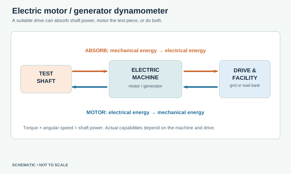
An electric dynamometer uses an electrical machine and power electronics to load or drive a test shaft. Depending on the design it can absorb mechanical power as a generator, supply mechanical power as a motor, or do both. It can be used for engines, electric motors, transmissions and vehicle powertrains. See Dynamometers.
Generating and absorbing
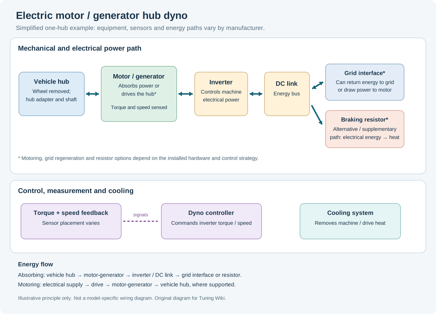
When the machine under test turns the dyno machine, its electromagnetic torque opposes rotation. Mechanical power is converted to electrical power, less machine and drive losses. The electrical energy can be dissipated in a suitably rated resistive load or, with a compatible regenerative drive and facility connection, returned to the supply. Braking resistors, converters and the electrical machine also produce heat and need appropriate cooling. Regeneration capability and recovered energy depend on the installed system; they are not automatic for every electric dyno.
Motoring and four quadrants
With a motor-capable drive, the dyno can turn the test shaft and supply torque. This makes engine cranking, overrun and externally driven portions of a transient cycle possible within the machine's ratings. Four-quadrant systems support combinations of positive and negative shaft speed with positive and negative torque: for either direction, torque can act with rotation (motoring) or against it (absorbing). A system described as an electric dynamometer is not necessarily four-quadrant. Power Test: AC Series Dynamometer; Parker: Engineered Motion Control Systems for Test Stands and Dynamometers.
Control and measurement
The drive regulates electrical machine torque or speed from controller commands. An in-line torque transducer can measure shaft torque, while a speed sensor provides angular velocity; the mechanical power at that shaft is their product. Electrical input or output power is a different measurement point and includes conversion losses, so electrical power alone is not equal to shaft power. Four-quadrant torque and power signs must be consistently defined in reports. See Dynamometer Control Systems.
Older installations may use DC machines with field control and suitable converters; contemporary systems frequently use AC machines with variable-frequency or vector-controlled drives. Both the machine and its drive determine the usable operating envelope. The machine's inertia, coupling and controller response affect transient results.
Uses and limits
Motoring enables richer transient tests, engine friction measurements under defined conditions and electric vehicle regeneration testing. Electric systems can provide stable controlled load and energy recovery, but require suitable electrical infrastructure, protection and cooling. Maximum torque, maximum speed, continuous and transient power, drive regeneration capacity and permissible operating quadrants must all be checked; a single headline power rating is insufficient. At standstill torque may be possible on an appropriately rated machine, but shaft power remains zero.
Unlike an eddy-current absorber, a motor-capable electric dyno can actively drive the test piece. Follow equipment-specific interlock, electrical isolation, guarding and emergency procedures.
Manufacturer example
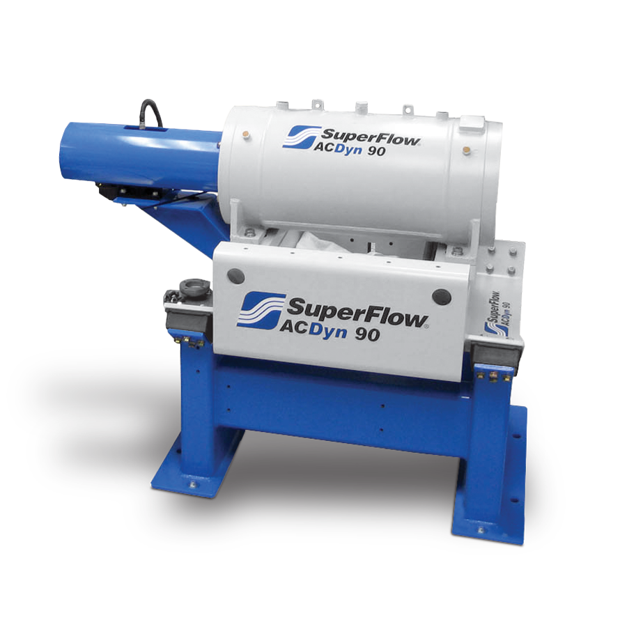
Example manufacturer: SuperFlow AC-series systems can absorb and apply shaft power; the manufacturer describes load-bank dissipation or regeneration as installation options.
How the machine and drive work together
A typical modern AC installation has a shaft-coupled electrical machine, a machine-side inverter, a DC link and a supply-side converter or controlled rectifier. The inverter regulates current and magnetic flux to command torque. When the test piece drives the machine against opposing torque, energy flows into the electrical system. A suitable regenerative supply interface can return some to the facility, a shared DC link can supply another compatible drive, or a rated resistor/load bank can dissipate it. Not all installations include every path; machine, drive and facility protection must be designed together. Parker's test-stand application note; Sierra CP powertrain systems.
Electrical conversion is not loss-free. Shaft power, inverter output, grid return and the test vehicle's battery power are different measurement points. Motors, converters, filters, cooling and auxiliary equipment consume part of the energy. Check the actual continuous rating and energy-flow arrangement instead of assuming all absorbed power reaches the grid.
Four-quadrant operation
With torque defined as the torque applied by the dynamometer to the test shaft, the sign of shaft power is torque multiplied by angular speed. The table uses one sign convention; some manufacturer screens report reaction torque with the opposite sign.
| Shaft speed | Dyno torque | Operation |
|---|---|---|
| Positive | Positive | Motoring: dyno supplies mechanical power. |
| Positive | Negative | Absorbing: dyno takes mechanical power. |
| Negative | Negative | Motoring in reverse. |
| Negative | Positive | Absorbing in reverse. |
A four-quadrant system is one able to work in all four combinations within its ratings. Grid regeneration and four-quadrant shaft control are related but separate capabilities: energy recovery needs a compatible electrical path. At zero speed a suitable machine may hold a rated torque for a permitted duration, while instantaneous mechanical shaft power remains zero.
Applications and what is measured
- Engine test cell: a motor-capable dyno can crank or externally drive an engine and run motoring/friction or overrun tests where the system permits. Define engine and dyno torque signs, shafts, temperatures and accessories.
- Electric and hybrid powertrain: a dyno can absorb traction output or, in a suitable motoring configuration, drive the shaft while the vehicle's motor applies regenerative braking. The vehicle's battery recovery is distinct from the dyno's return of absorbed power to the building supply.
- Hub and multi-axis testing: appropriately configured systems coordinate multiple motor/generator units to simulate loads or wheel-speed differences. Individual wheel control and steering simulation are options, not properties of every installation. See electric hub dynos.
- Road and transient simulation: a controller can apply a road-load or inertia model within the actual machine's bandwidth, power and stability limits. A passive absorber cannot independently drive the test shaft during an externally powered part of a cycle.
At the same shaft and instant, power (kW) = torque (N·m) × rpm ÷ 9,549.3. Use a calibrated shaft torque and speed at the stated measurement boundary; account for coupling inertia, gearbox ratio, losses and time alignment during transients. Summing independent hub outputs requires each hub's own signed torque and speed.
Examples and selection
SuperFlow AC-Series and Power Test AC-Series are engine-test examples for applying and absorbing shaft power; the latter describes load-bank dissipation or a regenerative supply option. ROTOTEST Energy is a hub-coupled four-quadrant example with front-end torque measurement and model-dependent controls. Their physical layout and energy path are not interchangeable merely because each uses an electric machine.
When specifying equipment, request the torque–speed curve for motoring and absorption, peak duration and continuous thermal limits, shaft inertia and speed, cooling, grid/export or load-bank rating, control bandwidth, encoder and torque-transducer specifications, interlocks and site integration. A peak headline figure does not establish continuous performance at every speed. See test setup and safety.
Sources
- Power Test: AC Series Dynamometer — absorption, motoring and regenerative options.
- Parker: Engineered Motion Control Systems for Test Stands and Dynamometers — four-quadrant drives.
- Yokogawa: Electric Motor Validation System — four-quadrant test applications.
Related guide: Electric motor and regenerative hub dynamometers — operation, energy recovery and manufacturer examples.
For examples of active test systems and controls, see AVL and Dyno One. Regeneration and motoring depend on the converter, supply and specific machine.